Foundation footing form and accessories

Inactive Publication Date: 2005-02-03
HUBER DONALD G +1
View PDF12 Cites 23 Cited by
  • Summary
  • Abstract
  • Description
  • Claims
  • Application Information

AI Technical Summary

Benefits of technology

[0024] The forms disclosed herein are water-resistant, light weight, easily placed in position, and relatively inexpensive. This application discloses a number of devices for placing and securing reinforcing bar within the forms and a means for leveling the form. The forms are easily stored, and mate

Problems solved by technology

The materials that are commonly used for concrete forms are easily damaged.
If steel forms are dented or bent, they are essentially useless.
Wood forms are difficult if not impossible to use over and over again.
Moreover, wood is a precious resource, and thus undesirable for use as a disposable form material.
Placing the reinforcing bar securing devices in the desired location within the form requires additional labor and some degree of skill.
Typically, when the concrete has hardened, the form is removed by a process that is labor intensive, and generally requires as much physical labor and cost as the initial set up.
Additionally, concrete can stick to the forming faces of wood, steel and other materials to the point where adequate cleaning is impossible.
Release from the concrete once it has set usually requires the use of a release agent or labor-intensive scraping which complicates the construction process.
In addition to the problems noted above, the concrete forms that are generally used for foundation footings can be difficult to handle because of their weight and bulk.
The forms must be

Method used


Image

  • Foundation footing form and accessories
  • Foundation footing form and accessories
  • Foundation footing form and accessories

Examples


Example

BEST MODE OF CARRYING OUT THE INVENTION

[0048] Turning now to the drawings, the forms and accessories will be described in preferred embodiments by reference to the numerals of the drawing figures wherein like numbers indicate like parts.

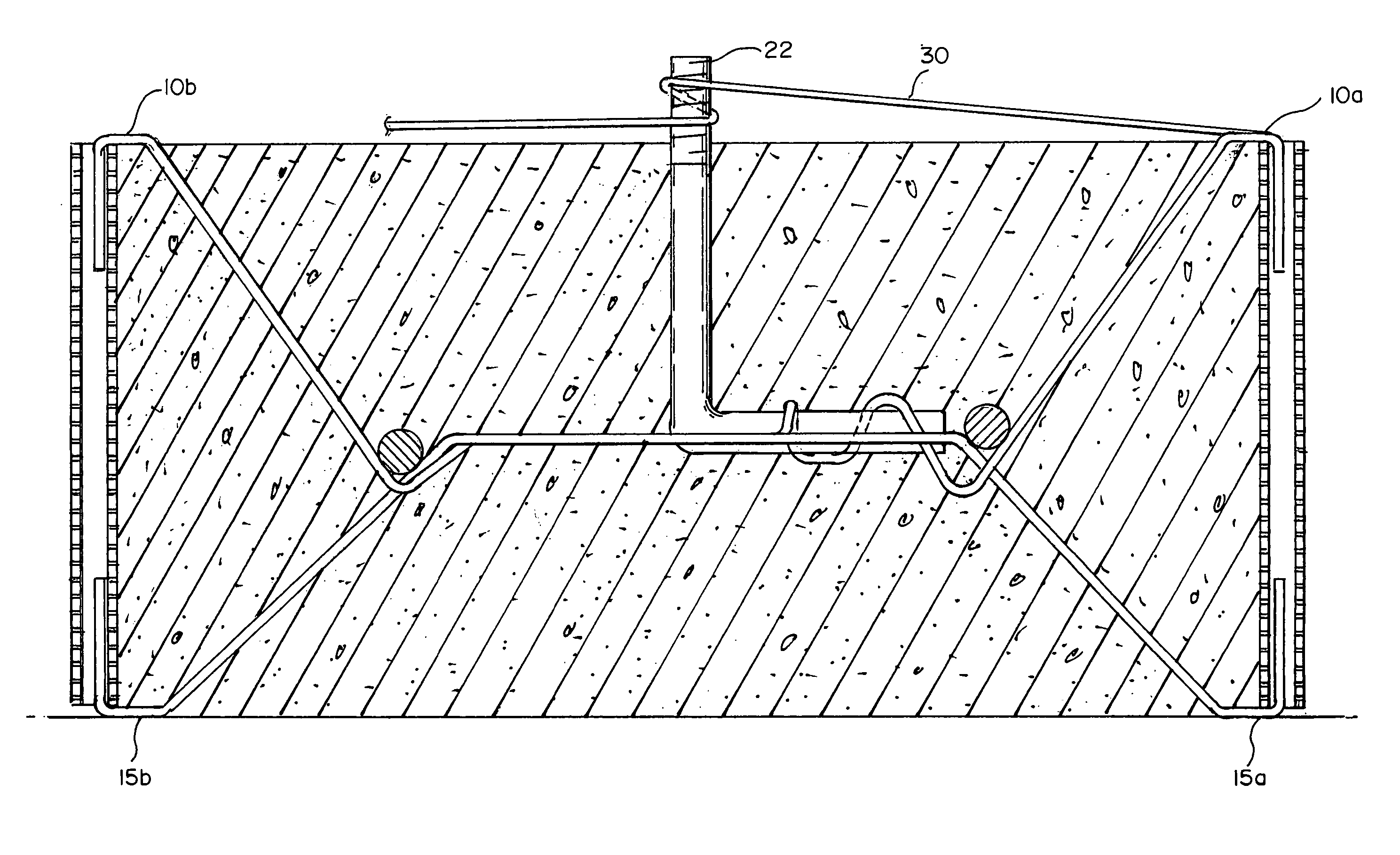
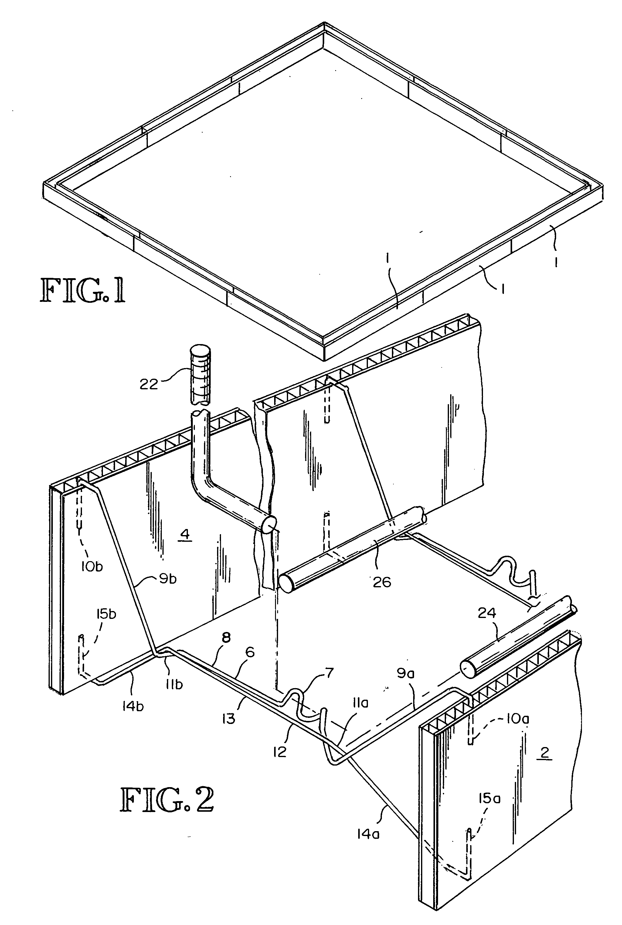
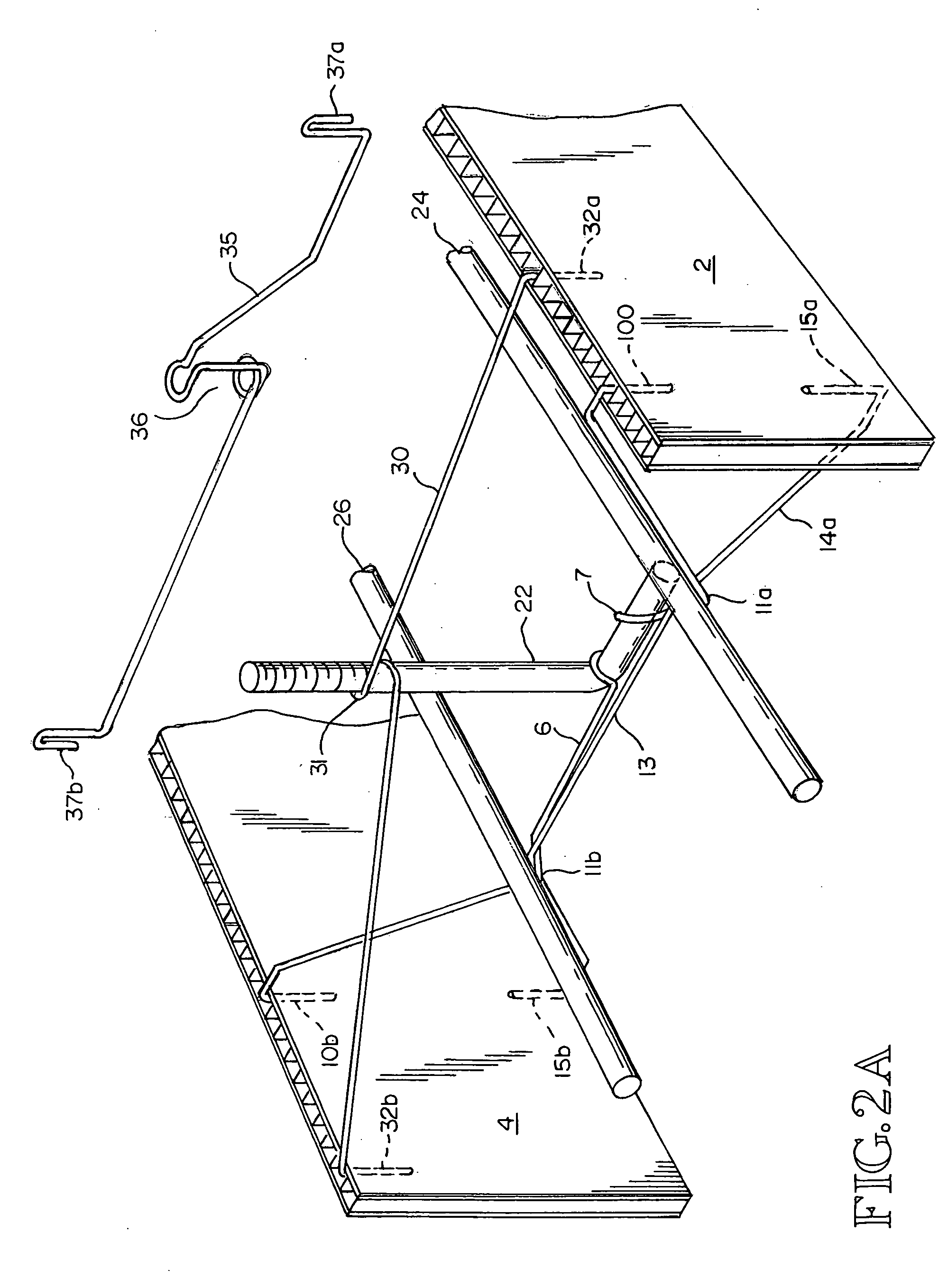
[0049]FIG. 1 shows a foundation footing form assembled from the form sections of the type that is disclosed herein. As seen in FIG. 2 the form sections of the embodiment depicted in the figure, have a pair of substantially planar side walls 2 and 4. The side walls are made from corrugated plastic having spaced, integral interconnecting ribs between two facing sheets. The channels or spaces between the interconnecting ribs are oriented at a right angle to the long axis of the form sections such that they are vertical when the form is placed on the substrate at a job site.

[0050] The side walls are connected by interconnecting top supports 6 and bottom supports 12, a plurality of which can be located along the length of the form section. In one prefe...


PUM

PropertyMeasurementUnit
Shapeaaaaaaaaaa
Widthaaaaaaaaaa
Areaaaaaaaaaaa

Abstract

Moisture resistant foundation footing form sections constructed from corrugated plastic are disclosed. Supports for holding sections of reinforcing bar, and connecting the side walls of the form sections are included. Also disclosed are tabs and notches in the side walls for use with stakes to connect adjacent form sections. Form sections are disclosed for constructing a corner in a foundation footing form. Step-down forms are disclosed for constructing a foundation footing form on a construction site having surfaces of different elevations. The form sections can be secured in position with stakes, and leveling devices for leveling the form once it is secured in position are disclosed. The form sections disclosed herein can be reused, but they do not attract insects and therefore they do not have to be removed from finished foundation footings.

Description

CROSS REFERRENCE TO RELATED APPLICATION [0001] This application claims the benefit of U.S. Provisional Application Ser. No. 60 / 480,896, entitled CONCRETE FORM FOR FOUNDATION FOOTING, filed Jun. 23, 2003.TECHNICAL FIELD [0002] The disclosure herein relates to an apparatus and method for forming concrete footings, for use in building construction. In particular, this document describes lightweight and collapsible forms, devices for holding re-enforcing bar in the forms, and a method for using the forms. BACKGROUND OF THE INVENTION [0003] In the art of building construction it is common practice to cast the base or foundation with concrete. A trench or excavation channel is prepared into which the forms, either made from steel or wood, are set up adjacent and connected to each other matching the dimensions of the required foundation (footing). The forms, which are steel panels or wooden boards or planks, are put into position on their edges across from each other and parallel to each o...

Claims


Application Information

Patent Timeline
IPC IPC(8): E02D27/01E04B1/41E04B1/61E04B2/86E04C5/16E04G9/05E04G13/00E04G13/02E04G17/00E04G17/12E04G21/18
CPCE02D27/01E04G21/185E04B1/6179E04B2/8635E04B2/8652E04B2001/4192E04B2001/6195E04B2002/867E04B2002/8676E04C5/166E04C5/167E04C5/168E04G9/05E04G13/00E04G13/02E04G17/001E04G17/12E04B1/4157
Inventor HUBER, DONALD G.HARTMAN, TERRY SCOTT
Owner HUBER DONALD G
Why Eureka
Try Eureka