Cabling system and method for facilitating fluid three-dimensional movement of a suspended camera

a three-dimensional movement and cable system technology, applied in the field of aerial cable rail systems, can solve problems such as trivial control of objects

Inactive Publication Date: 2005-02-03
FORTRESS CREDIT CORP AS AGENT
View PDF29 Cites 36 Cited by
  • Summary
  • Abstract
  • Description
  • Claims
  • Application Information

AI Technical Summary

Benefits of technology

[0015] Embodiments of the invention are ideally suited for use filming movies, sporting events, or any other activity that requires fluid movement of a camera or other object to any position within a defined volume of space. To accomplish such positioning embodiments of the invention are configured to move an object throughout three-dimensional space by relocating one or more lines that are feed through a plurality of sides of the object. These line(s) (e.g., a cable, rope, string, cord, wire, or any other flexible connective material) which support the object over a volume of space are arranged in way that allows the object to be rapidly moved to and from any location within the defined volume of space. For instance, the system may be arranged to perform three-dimensional movement using one line configured as an endless loop, one line configured as a half loop, two lines configured as endless loops or two lines configured as half loops.
[0018] In an embodiment of the invention configured for example in a rectangular configuration with four regions having any appropriate number of line support elements, the supported object is moved along the X-axis independently of movement along the Y-axis and therefore requires no complex control system. In this example, the Z-axis movement follows an ellipsoidal path (four foci ellipsoidal where the foci are the supports) that can be as flat or circular as desired depending on the shape of the area of coverage desired. In the case of an area of coverage over a physical potential well, for example a stadium or open pit mine that is deeper in the middle than on the sides, the X-axis and Y-axis motion can be configured with more or less line in the system to create a flatter or rounder elliptical shape in order to avoid the surface below since the Z-axis automatically traverses vertically when the object moves towards the sides of the area of coverage of the invention. The ellipsoidal path can be as flat or circular as desired depending upon the amount of line deployed in the system and the relative height of the supports. Displacing equal lengths of line into a plurality of sides of the supported object allows the Z-axis of the platform to be traversed which results in trivial control of the object. This technique of relocating line without the need for a control system in order to move an object in three dimensions provides many advantages over the prior art that requires complex control software and active stabilization.
[0019] Embodiments of the invention can also use a three support triangular configuration where no two sides are required to be the same length. For any topology that embodiments of the invention are configured, there is no ratcheting movement at the object since the same line supports an object on a plurality of sides with the object freely moving to the point of minimal potential energy based on the amount of line transferred from one side to another side of the supported object. In addition, the lengths of the line do not require adjustment in way that requires complex calculations and computer control since the junctions effecting movement of each axis are independently operated.
[0024] The term line as used herein refers to a continuous and unbroken length of line that can bend and be directed through any number of passive or powered or active line support elements or any other redirection mechanism. In one embodiment of the invention line breakage causes components associated with the line to become nonfunctional. To avoid this issue and thereby enhance system safety, the invention contemplates the use of a limiting mechanism to keep a supported object from making contact with the area of coverage. By supporting an object on a plurality of sides with a single line, there is a built in safety characteristic not found in the prior art whereby one line may break without causing the supported object to contact the ground below.
[0027] Some examples of the type of line embodiments of the invention that may be utilized include synthetic rope fibers such as but not limited to HMDPE (High Molecular Density Polyethylene) fibers such as Spectra, or improved fibers such as Vectran. Line of this length, strength and weight allows the platform to be deployed over large distances. Synthetic line is 90 percent as strong as cable while having 10 percent of the weight.

Problems solved by technology

Displacing equal lengths of line into a plurality of sides of the supported object allows the Z-axis of the platform to be traversed which results in trivial control of the object.

Method used


Image

  • Cabling system and method for facilitating fluid three-dimensional movement of a suspended camera
  • Cabling system and method for facilitating fluid three-dimensional movement of a suspended camera
  • Cabling system and method for facilitating fluid three-dimensional movement of a suspended camera

Examples


Embodiment Construction

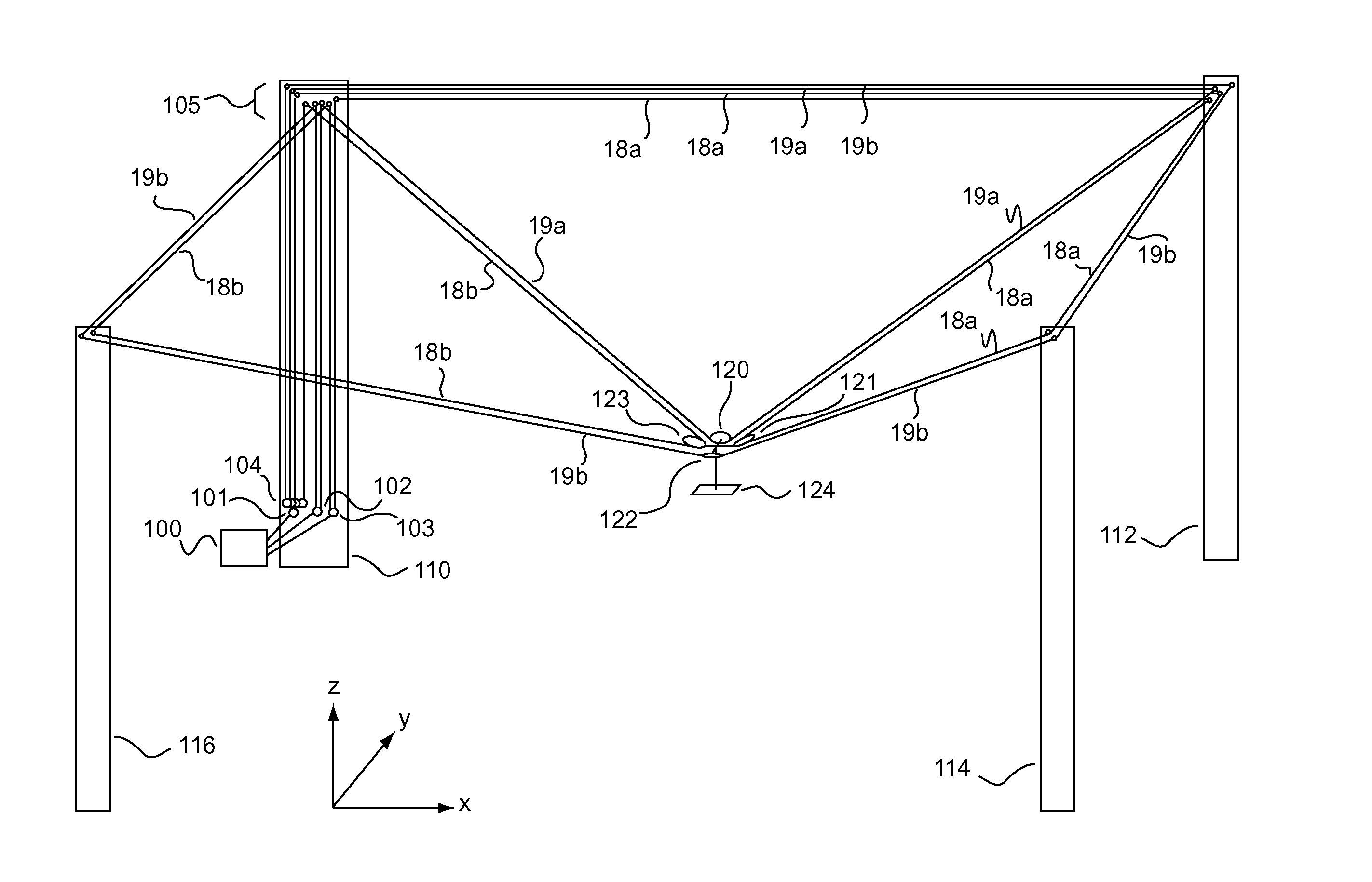
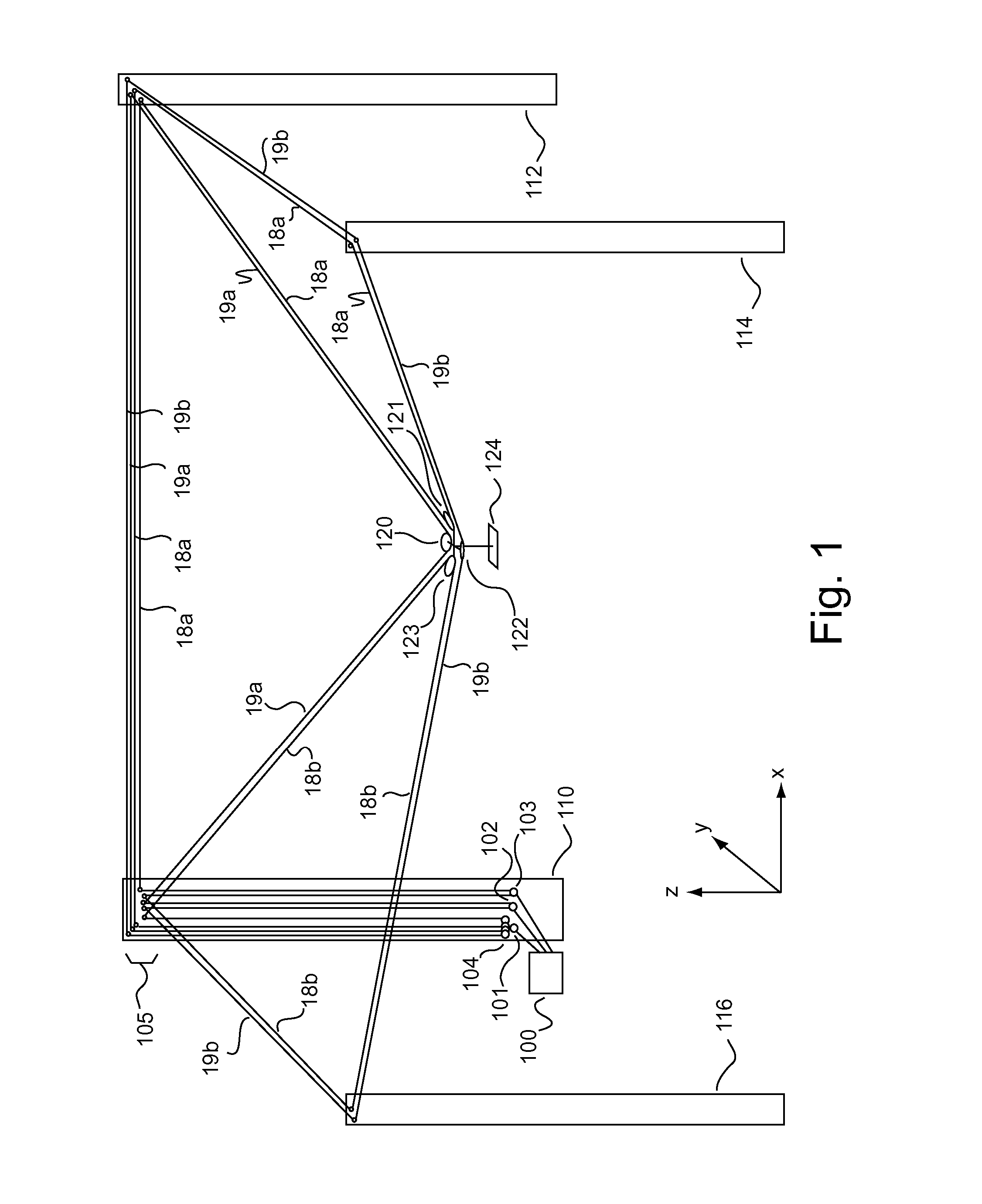
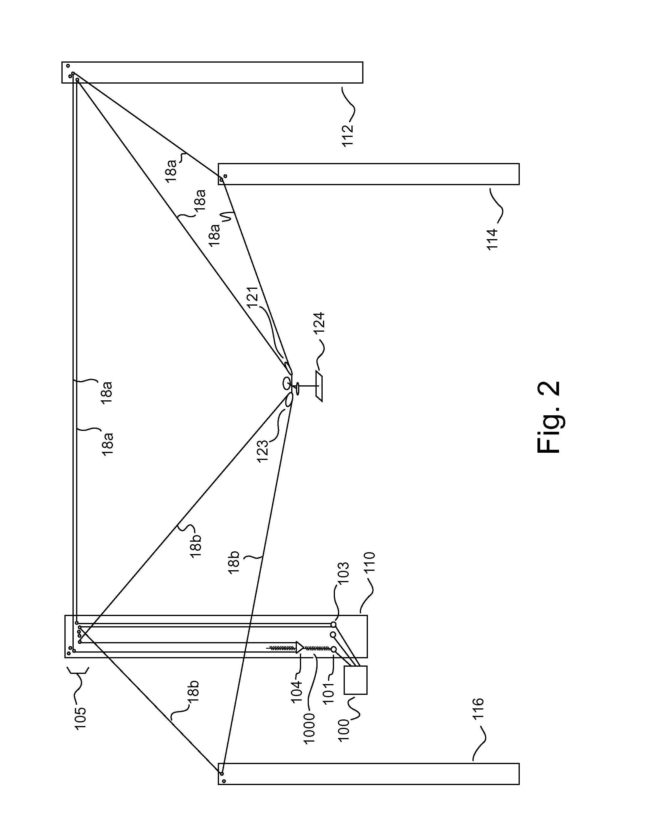
[0046] Embodiments of the invention relate to a cabling system and method for facilitating fluid three-dimensional movement of a suspended camera or other object. In the following description, numerous specific details are set forth to provide a more thorough description of embodiments of the invention. It will be apparent, however, to one skilled in the art, that the invention may be practiced without these specific details. In other instances, well known features have not been described in detail so as not to obscure the invention. However, in each instance the claims and the full scope of any equivalents are what define the metes and bounds of the invention.

[0047] Embodiments of the invention move an object throughout three-dimensional space by relocating line coupled with a plurality of sides of the object. In an embodiment utilizing two lines, once the displacement height of the platform is set to a minimum value for a coverage area, if one line breaks, the supported platform ...


PUM


Abstract

Embodiments of the invention are ideally suited for use filming movies, sporting events, or any other activity that requires fluid movement of a camera or other object to any position within a defined volume of space. To accomplish such positioning embodiments of the invention are configured to move an object throughout three-dimensional space by relocating one or more lines that are feed through a plurality of opposing sides of the object. These line(s) (e.g., a cable, rope, string, cord, wire, or any other flexible connective element) which support the object over a volume of space are arranged in way that allows the object to be rapidly moved to and from any location within the defined volume of space. For instance, the system may be arranged to perform dimensional movement using one line configured as an endless loop, one line configured as a half loop, two lines configured as endless loops or two lines configured as half loops.

Description

[0001] This application is a continuation in part of U.S. patent application Ser. No. 10 / 604,525, filed on Jul. 28, 2003 entitled “System and Method for Moving Objects within Three-Dimensional Space” which is hereby incorporated by reference.BACKGROUND OF INVENTION [0002] 1. Field of the Invention [0003] Embodiments of the invention described herein pertain to the field of aerial cable rail systems that enable the fluid movement of a suspended camera or other object within three-dimensional space. [0004] 2. Description of the Related Art [0005] An aerial cable rail system is a system based on an elevated cable or rope, along which objects are transported. Existing cable rail systems rely on large fixed structures and / or complex control systems in order to facilitate the movement of objects. Many of these systems are impractical or difficult to use in that such systems typically fail to satisfactorily achieve the full spectrum of platform stability, ease of control, a compact footpri...

Claims


Application Information

Patent Timeline
Patent Type & Authority Applications(United States)
IPC IPC(8): B64C17/06B66C13/08
CPCF16M11/42F16M11/045F16M11/425F16M11/048F16M11/18F16M11/046
Inventor RODNUNSKY, JIM
Owner FORTRESS CREDIT CORP AS AGENT
Why Eureka
Try Eureka