Guided wave radar level transmitter with automatic velocity compensation

Active Publication Date: 2005-02-03
AMETEK MAGNETROL USA LLC
View PDF16 Cites 46 Cited by
  • Summary
  • Abstract
  • Description
  • Claims
  • Application Information

AI Technical Summary

Benefits of technology

[0010] Broadly, in accordance with one aspect of the invention there is disclosed a guided wave radar transmitter comprising a probe defining a transmission line including a relatively low impedance change target marker above an expected sensing region of the probe. A pulse circuit is connected to the probe for generating pulses on the transmission line and receiving a reflected signal from the transmission line. The reflected signal selectively includes a target pulse representing the target marker and a level pulse representing material along the length of the probe. A controller is operatively connected to the pulse circuit. The controller normally operates at a relatively low gain to determine a level time to the level pulse to determine material level, and periodically operates at a relatively high gain to determine a target time to the target pulse. The target time is used to compensate the level time for properties of vapor above the material level.
[0011] There is disclosed in accordance with another aspect of the invention a time domain reflectometry measurement instrument including a probe defining a transmission line and including a reference marker proximate a top end of the probe and a relatively low impedance change target marker above an expected sensing region of the probe. A pulse circuit is connected to the probe for generating pulses on the transmission line and receiving a reflected signal from the transmission line. The reflected signal selectively includes a fiducial pulse representing the reference marker, a target pulse representing the target marker and a level pulse representing material along the length of the probe. A time sampling circuit is connected to the pulse circuit for developing a time representation of the reflected signal. A controller is operatively connected to the pulse circuit

Problems solved by technology

However, these devices are analog devices limited in the ability to measure the level of extremely low dielectric materials, or materials that coat, clump or build up on the probe, over the

Method used


Image

  • Guided wave radar level transmitter with automatic velocity compensation
  • Guided wave radar level transmitter with automatic velocity compensation
  • Guided wave radar level transmitter with automatic velocity compensation

Examples


Example

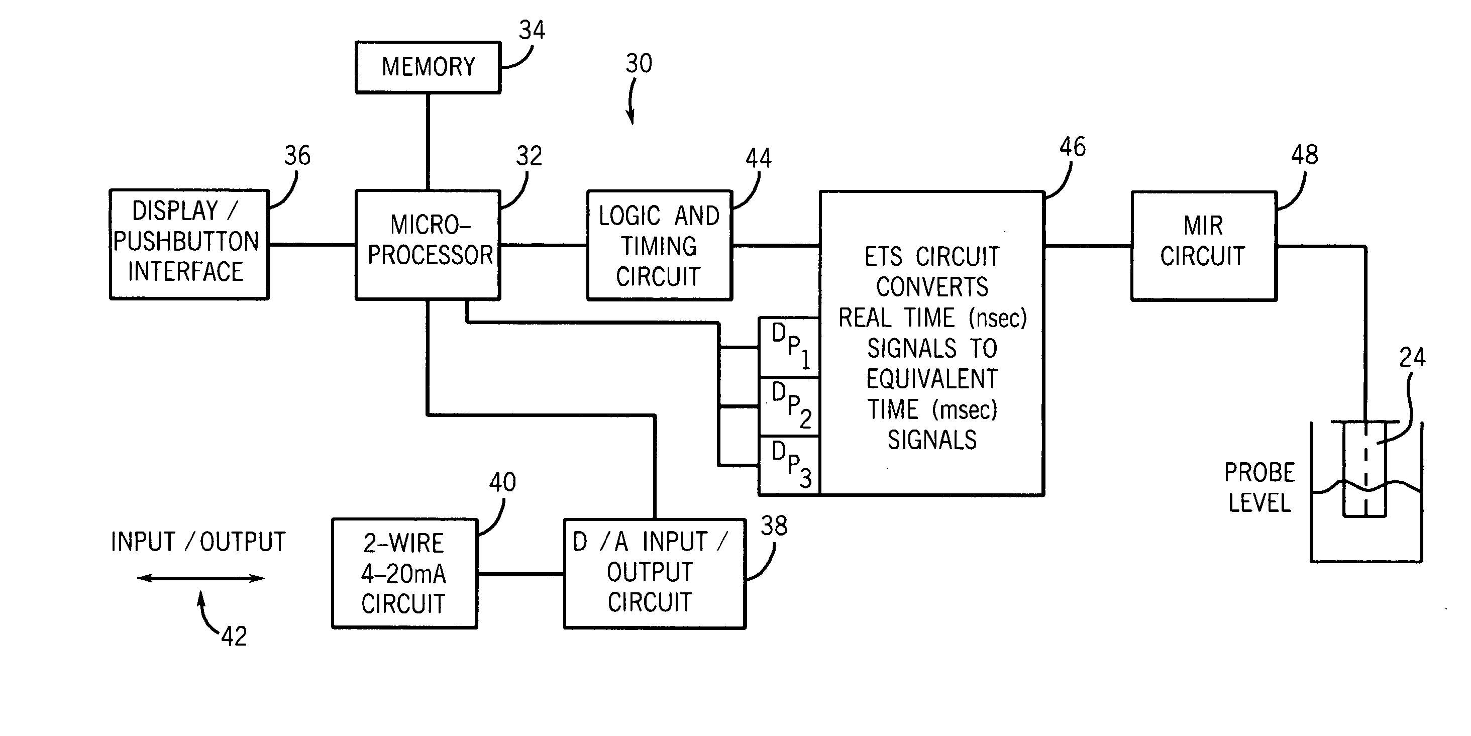
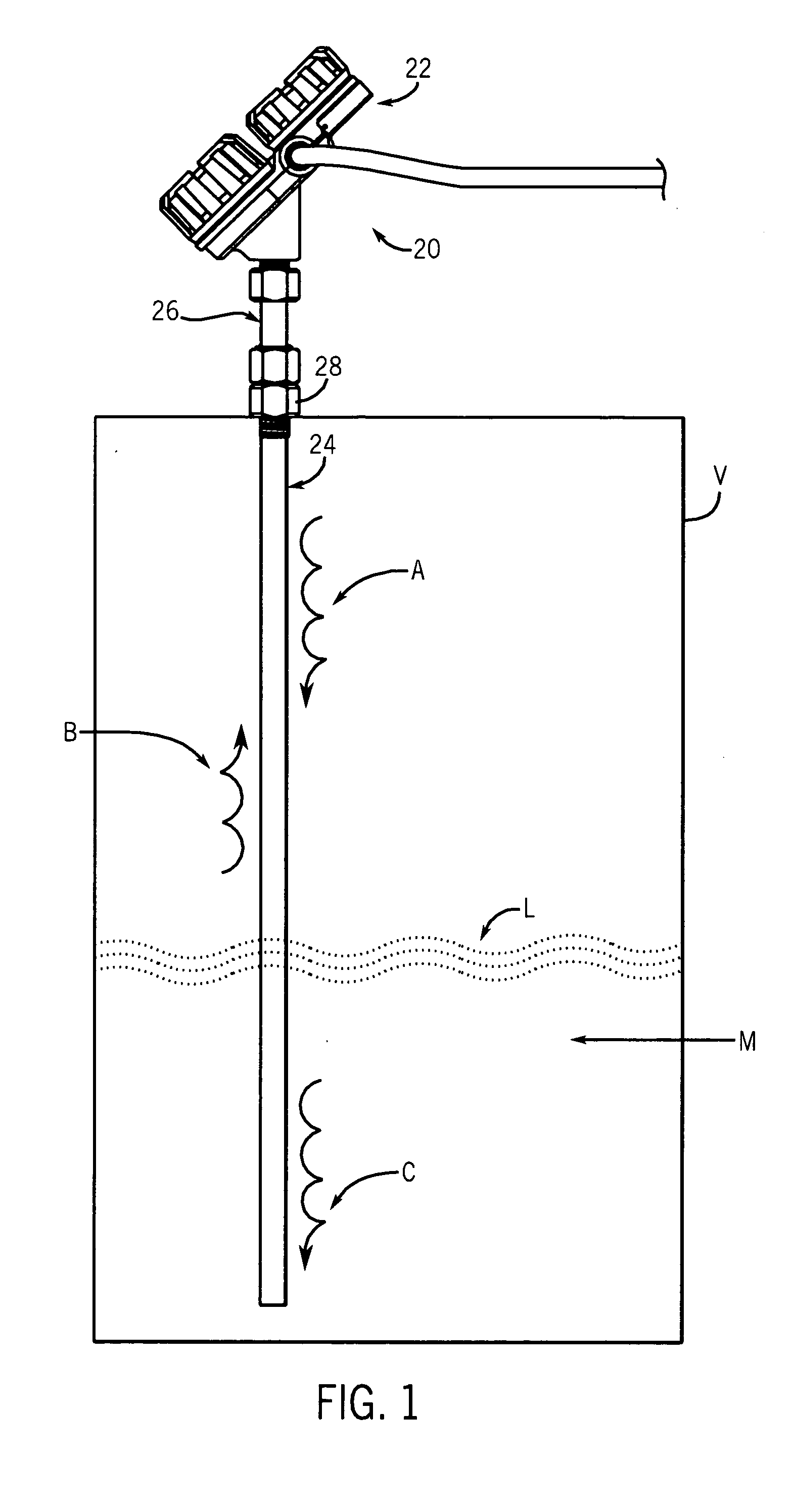
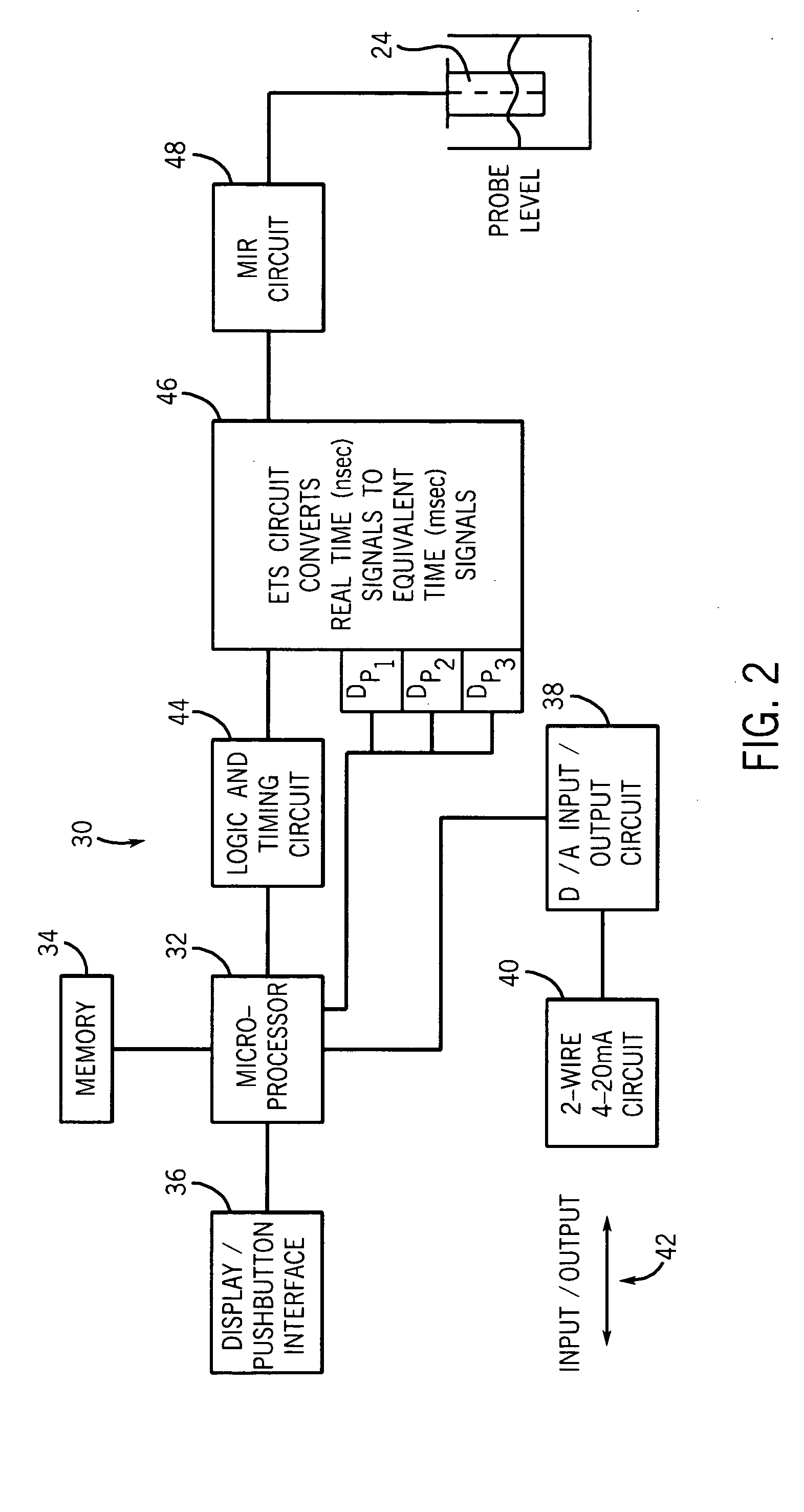
[0021] Referring to FIG. 1, a process instrument 20 according to the invention is illustrated. The process instrument 20 uses micropower impulse radar (MIR) in conjunction with equivalent time sampling (ETS) and ultra-wide band (UWB) transceivers for measuring level using time domain reflectometry (TDR). Particularly, the instrument 20 uses guided wave radar for sensing level. While the embodiment described herein relates to an MIR level sensing apparatus, various aspects of the invention may be used with other types of process instruments for measuring various process parameters.

[0022] The process instrument 20 includes a control housing 22, a probe 24, and a connector 26 for connecting the probe 24 to the housing 22. The probe 24 is typically mounted to a process vessel V using a threaded fitting 28. Alternatively, a flange may be used. The housing 22 is then secured to the probe 24 as by threading the connector 26 to the probe 24 and also to the housing 22. These components may ...


PUM


Abstract

A guided wave radar transmitter comprises a probe defining a transmission line including a relatively low impedance target marker above an expected sensing region of the probe. A pulse circuit is connected to the probe for generating pulses on the transmission line and receiving a reflected signal from the transmission line. The reflected signal selectively includes a target pulse representing the target marker and a level pulse representing material along the length of the probe. A controller is operatively connected to the pulse circuit. The controller normally operates at a relatively low gain to determine a level time to the level pulse to determine material level, and periodically operates at a relatively high gain to determine a target time to the target pulse. The target time is used to compensate the level time for properties of vapor above the material level.

Description

FIELD OF THE INVENTION [0001] This invention relates to an apparatus and method utilizing guided wave radar for measuring the condition or characteristics of a material, and more particularly to automatic velocity compensation. BACKGROUND OF THE INVENTION [0002] Knowledge of level in industrial process tanks or vessels has long been required for safe and cost-effective operation of plants. Many technologies exist for making level measurements. These include buoyancy, capacitance, ultrasonic and microwave radar, to name a few. Recent advantages in micropower impulse radar (MIR), also known as ultra-wide band (UWB) radar, in conjunction with advances in equivalent time sampling (ETS), permit development of low power and low cost time domain reflectometry (TDR) devices. [0003] In a TDR instrument, a very fast stream of pulses with a rise time of 500 picoseconds, or less, is propagated down a transmission line that serves as a probe in a vessel. The pulses are reflected by a discontinui...

Claims


Application Information

Patent Timeline
IPC IPC(8): G01F23/284G01S7/34G01S7/40G01S13/02
CPCG01F23/284G01S7/34G01S2007/4078G01S13/0209G01S7/4021G01S13/88G01S7/4078
Inventor BERRY, JAMES M.GARD, ALAN M.
Owner AMETEK MAGNETROL USA LLC
Why Eureka
Try Eureka