Method to make a planar writer with low D.C. coil resistance

a technology of planar writing and coil resistance, which is applied in the direction of metal sheet core head, data recording, instruments, etc., can solve the problems of large corresponding increase in heating, thermal tip protrusion, and prior art does not teach specifically a method of improving magneto-motive force, so as to reduce power consumption and reduce thermal tip protrusion , the effect of not sacrificing the magneto-motive force required

Inactive Publication Date: 2005-02-03
HEADWAY TECH INC
View PDF7 Cites 6 Cited by
  • Summary
  • Abstract
  • Description
  • Claims
  • Application Information

AI Technical Summary

Benefits of technology

[0010] The first object of this invention is to provide a write head with reduced power consumption and a corresponding reduction in thermal tip protrusion, while not sacrificing the magnetomotive force required to write data at high densities.
[0011] The second object of this invention is to provide such a write head without sacrificing space within the write head structure and to maintain, thereby, a small size.

Problems solved by technology

If write head performance is to be improved by increasing the current, there will be a large corresponding increase in heating and the problem of thermal protrusion of the pole tip.
Thermal tip protrusion is a major problem since the write head must be positioned increasingly close to the medium surface as written densities become greater.
The challenge in writer design, therefore, is how to make a writer with a greater number of coil turns, while keeping the total coil resistance low and maintaining the same length of the yoke.
With the exception of the method of Hong et al., cited above, the prior art does not teach specifically a method of improving the magneto-motive force of a write head while retaining its general structure and dimensions.

Method used


Image

  • Method to make a planar writer with low D.C. coil resistance
  • Method to make a planar writer with low D.C. coil resistance
  • Method to make a planar writer with low D.C. coil resistance

Examples


Embodiment Construction

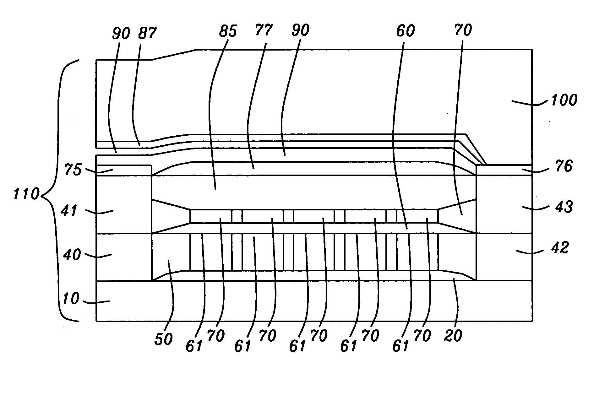
[0029] The preferred embodiment teaches a method of forming an inductive write head having two connected planar coil layers and a reduced coil resistance resulting from the greater height and resultant greater cross-sectional area of the lower coil windings. The coil layers are formed in horizontal planes, vertically separated, and insulated from each other by a minimal thickness of insulation and connected through vias (not shown) that pass between the insulating layers. The methods of the present invention are generally applicable and will allow the fabrication of a write head having the same height and width dimensions and total coil length, yet a smaller coil resistance.

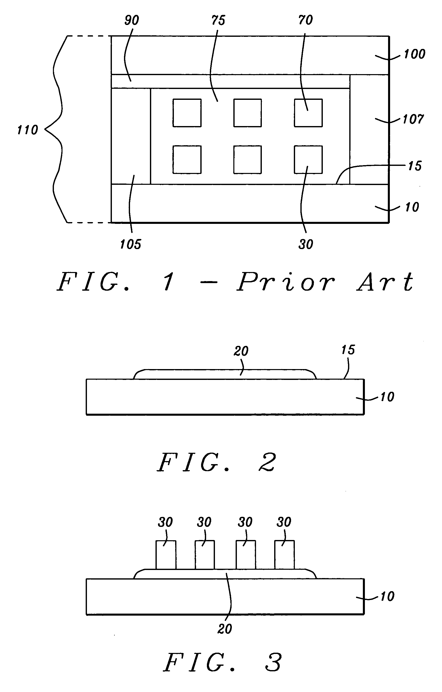
[0030] Referring first to FIG. 1, there is shown, schematically, a prior art write head of the type whose performance is materially improved by the methods of the present invention, together with a brief description of its pertinent components to simplify the identification of the components of the present inven...


PUM

PropertyMeasurementUnit
thicknessaaaaaaaaaa
thicknessaaaaaaaaaa
heightaaaaaaaaaa

Abstract

An inductive-type write head and its method of fabrication are disclosed. The write head has a vertically separated two-element planar coil of reduced resistance which is the result of forming the lower of the two coils with windings of a greater height and substantially larger cross-sectional area than those of the upper coil. The formation of a lower coil with greater height is possible because of a surface planarization that allows separating the coils by an alumina layer of minimal thickness. This method allows the reduction of coil resistance without the necessity of enlarging the head dimensions. The reduced resistance results in lower power consumption and the elimination of pole tip protrusion caused by excessive heating during operation.

Description

BACKGROUND OF THE INVENTION [0001] 1. Field of the Invention [0002] This invention relates to thin film magnetic write head fabrication, in particular to the fabrication of such a write head that minimizes thermal pole-tip protrusion with a coil configuration that provides low power consumption for a given yoke length. [0003] 2. Description of the Related Art [0004] Thin film induction-type magnetic write heads are used to encode magnetically stored information on moving magnetic media such as tapes and discs. In the simplest terms, such a head consists of two pole pieces separated at the air-bearing surface (ABS) by a narrow gap (the write gap) and yoked together behind the ABS to form an approximately horseshoe-shaped assembly. A conductive coil is patterned between the pole pieces which, when electrically energized, induces a magnetic field between the poles that fringes across the gap. It is this induced field that encodes small magnetic regions in the moving medium. In the most...

Claims


Application Information

Patent Timeline
Patent Type & Authority Applications(United States)
IPC IPC(8): G11B5/127G11B5/147G11B5/31
CPCG11B5/127G11B5/147G11B5/3196G11B5/3136G11B5/31
Inventor HAN, CHERNG-CHYIYANG, DANNINGCHEN, MAO-MIN
Owner HEADWAY TECH INC
Why Eureka
Try Eureka