

Pop and click reduction using DAC power up and power down processing
- Summary
- Abstract
- Description
- Claims
- Application Information
AI Technical Summary
Problems solved by technology
Method used
Image

Examples
Embodiment Construction
[0018] The embodiments of the present invention may be practiced in a variety of amplifiers, including those amplifiers that utilize a DC (direct current) blocking capacitor. In the following description, a particular audio amplifier is described driving a load, such as a low impedance load. An example of a low impedance audio load is a headphone (HP). The signal being coupled to the load is an audio signal, generally above 20 Hz. However, the embodiments of the invention may be employed and practiced in other types of amplifiers as well and not limited to the particular embodiments described below.
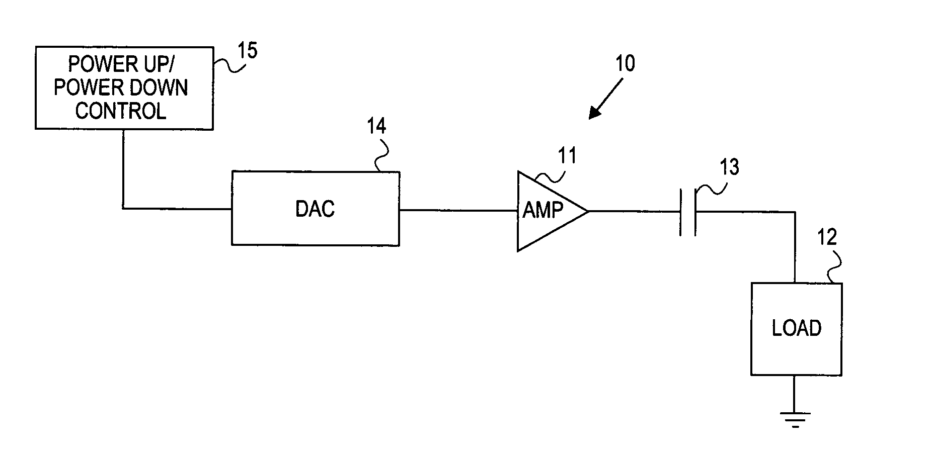
[0019] Referring to FIG. 1, an example circuit 10 is shown in which an amplifier 11 is coupled to a load 12 through a DC blocking capacitor 13. In the particular embodiment of circuit 10, amplifier 11 may be used as an audio amplifier to drive an audio signal to a load 12, which may be a low impedance load. One example of a low impedance load is a headphone, which may have an impedance i...
PUM
 Abstract
Description
Claims
Application Information