Pavement marker with enhanced daytime signal

a daytime signal and enhancement technology, applied in signalling systems, roads, constructions, etc., can solve the problems of not being perceived by drivers and retroreflecting daytime light, and achieve the effect of reducing the strength of the nighttime signal produced by the front retroreflective panel, reducing the nighttime effectiveness, and increasing the density of energy directors

Inactive Publication Date: 2005-02-03
ENNIS PAINT
View PDF8 Cites 20 Cited by
  • Summary
  • Abstract
  • Description
  • Claims
  • Application Information

AI Technical Summary

Benefits of technology

[0018] The strength of a nighttime signal produced by the front retroreflective panel is reduced as the density of energy directors increases. Normally there is no incentive to reduce the nighttime effectiveness of the retroreflective panel on a pavement marker. However, traffic control devices, such as pavement markers, typically are used in close proximity to one another through construction zones. As a result, an adequate nighttime signal can be produced in a construction zone due to the closer spacing between pavement, markers: typically employed in a construction zone. On the other hand, stronger daylight signals in construction zones would be helpful. Similarly, a stronger daytime signal would be helpful in school zones to correspond to the times when children are likely to be present. The strength of the daylight signal is enhanced by adding the fluorescence of the energy directors to the edge glow of the top and / or the reflective or fluorescent optical signal produced by the base.

Problems solved by technology

However, under normal conditions this retroreflected daytime light will be small and will not be perceived by a driver.

Method used


Image

  • Pavement marker with enhanced daytime signal
  • Pavement marker with enhanced daytime signal
  • Pavement marker with enhanced daytime signal

Examples


Embodiment Construction

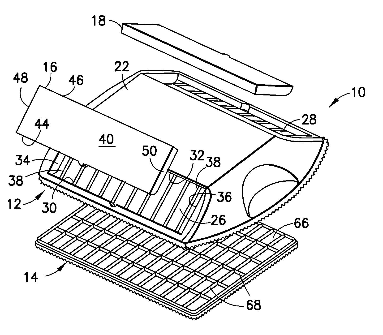
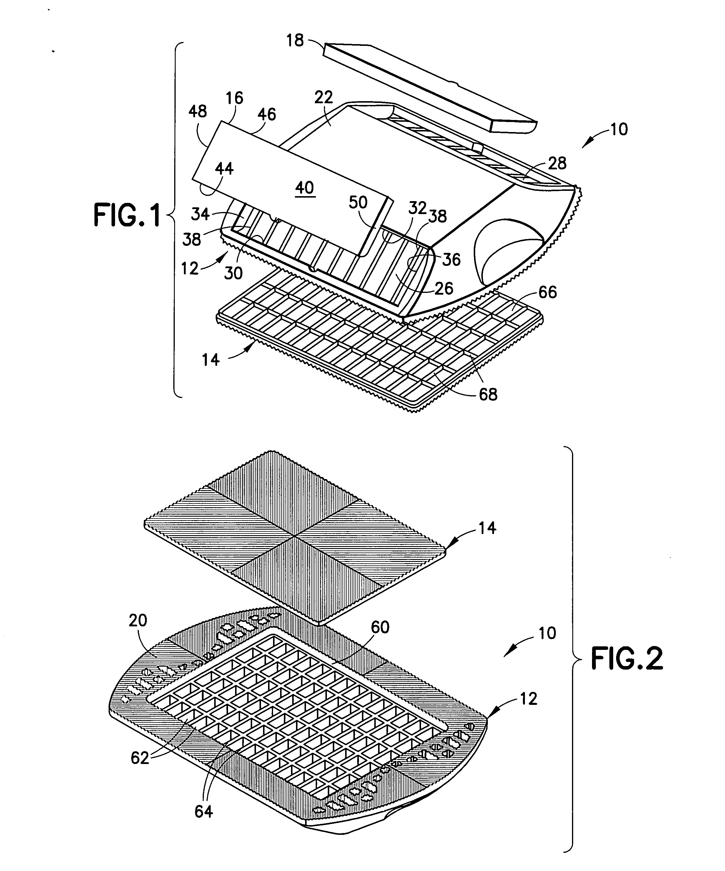
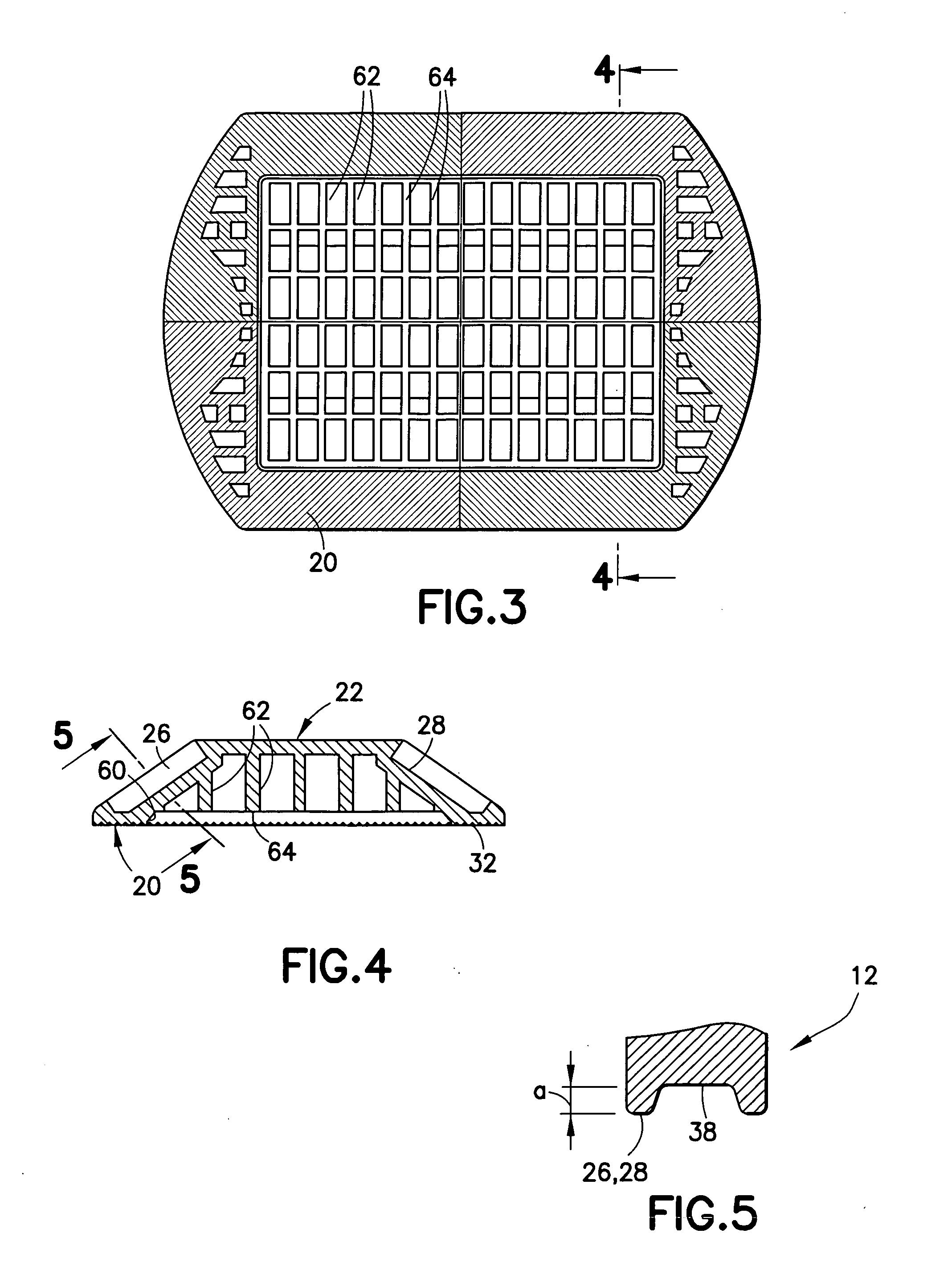
[0031] A pavement marker in accordance with the subject invention is identified generally by the numeral 10 in FIGS. 1-12. The pavement marker 10 includes a base 12, a bottom cover 14 and front and rear lenses 16 and 18. The base 12 is molded unitarily from an opaque fluorescent thermoplastic material and includes a bottom 20, as shown most clearly in FIG. 2 and an opposed top 22 as shown most clearly in FIG. 1. The top 22 is formed with front and rear lens recesses 26 and 28 for receiving the front and rear lenses 16 and 18 respectively. The lens recesses 26 and 28 are substantially identical. In many embodiments only a front lens 16 will be required, and hence the base will have no rear lens recess 28. Thus, for convenience only the front lens recess 26 is described in detail herein. More particularly, the front lens recess 26 defines a substantially wide rectangle with a bottom edge 30, a top edge 32 and opposite side edges 34 and 36. The front lens recess 26 is sloped relative t...


PUM


Abstract

A pavement marker includes a base and at least one lens with retroreflective areas aligned to reflect headlights back toward a vehicle for producing a nighttime signal. The lens and/or the base are formed from resins that include a fluorescent material. At least a portion of the lens is free of the retroreflective areas so that the fluorescent material of the lens and/or the base produces a daytime signal emitted from or through the lens.

Description

BACKGROUND OF THE INVENTION [0001] 1. Field of the Invention [0002] The invention relates to a pavement marker that reflects and / or transmits light to identify selected regions of a driving lane. [0003] 2. Description of the Related Art [0004] Traffic safety engineers design roads to give drivers a limited and predictable range of visual cues in an effort to generate predictable responses to those cues. The visual cues relate primarily to the shapes, colors and locations of traffic control devices. Standards for traffic control devices are specified in the Manual of Uniform Traffic Control Devices (MUTCD). The colors employed most widely in traffic control devices are white, red, yellow, fluorescent yellow-green and fluorescent orange. [0005] White traffic control devices typically are employed on the traffic lane markings to identify the right edge of a travel lane or the demarcation between two travel lanes that permit travel flow in the same direction. Yellow is a warning indicat...

Claims


Application Information

Patent Timeline
Patent Type & Authority Applications(United States)
IPC IPC(8): E01F9/06
CPCE01F9/06E01F9/553E01F9/524E01F9/588
Inventor SNAGEL, PAUL
Owner ENNIS PAINT
Why Eureka
Try Eureka