
Cutting plate for a drill bit

a drill bit and cutting plate technology, applied in the field of cutting plates for drill bits, can solve the problems of rotary cutting of ceramic tiles, requiring drill bits of different fixed diameters, brittle sharp cutting edges, and prone to chipping, so as to reduce the chance of chipping of cutting edges, increase cutting speed, and reduce the chance of breakage

Active Publication Date: 2005-02-03
BLACK & DECKER INC
View PDF28 Cites 8 Cited by
  • Summary
  • Abstract
  • Description
  • Claims
  • Application Information

AI Technical Summary

Benefits of technology

[0011] Thus, the parallelogram circumscribed by the first and second faces can be any parallelogram shape ranging from a partially collapsed parallelogram, with sharp cutting edges, up to and including, a rectangle with four right-angled edges. The closer the parallelogram resembles a rectangle the greater the enclosed area therein and the stronger the cutting plate at its foremost working end. This makes the cutting plate more resistant to breakage caused by a chipped cutting edge. Thus the cutting edges can be orientated with respect to the workpiece in a more aggressive manner to increase speed of cutting while limiting the chance of chipping the cutting edges to an acceptable level.
[0012] Preferably a chisel edge is defined by the intersection of one of the pair of first or second faces at the foremost of the working end. The chisel edge provides an edge to penetrate the outer layer of a workpiece to begin the hole cutting process. A chisel edge at the foremost end of the cutting plate is less brittle than a single cutting point and is therefore less prone to chipping. The length of the chisel edge is defined by the other of the pair of first or second faces. If the chisel edge is chipped then it can be re-sharpened by grinding either of both of the pair of first or second faces.
[0014] Preferably, the transitional edge between each first face and a respective rotationally leading second face is a primary cutting edge. Also, a transitional edge between each second face and a respective rotationally leading front face is a secondary cutting edge. The primary and secondary cutting edges can be continuous, but need not be for satisfactory cutting of a workpiece. The second and first faces provide relief to the primary and secondary cutting edges, respectively.
[0017] Preferably, the cutting plate further comprises a mechanism for precise attachment of the cutting plate to a shank of a drill bit. Such an attachment mechanism is useful for easily and reliably attaching the cutting plate to a shank of a drill bit. Thus, the axes of rotation of the cutting plate and shank are concentric.

Problems solved by technology

Rotary cutting of a ceramic tile presents various difficulties because of the hardness and smoothness of both the glazed protective layer of the tile and the tile substrate material itself.
However, this known method suffers from the drawback that several drill bits of different fixed diameters are required in order to cut a hole in the tile to a desired diameter.
Such sharp cutting edges are also brittle and more prone to chipping.
This is especially problematic at the foremost working end of the drill bit in the region of the chisel edge where the cutting plate's geometry is small and there is not enough spare material to re-sharpen chipped cutting edges more than a few times, if at all.
This reduces the life span of the drill bit.
In this case breakage of the cutting edges could result complete removal of the foremost working end of the cutting plate making its re-sharpening impossible.

Method used


Image

  • Cutting plate for a drill bit
  • Cutting plate for a drill bit
  • Cutting plate for a drill bit

Examples


Embodiment Construction

[0031] The following description of the preferred embodiment(s) is merely exemplary in nature and is in no way intended to limit the invention, its application, or uses.

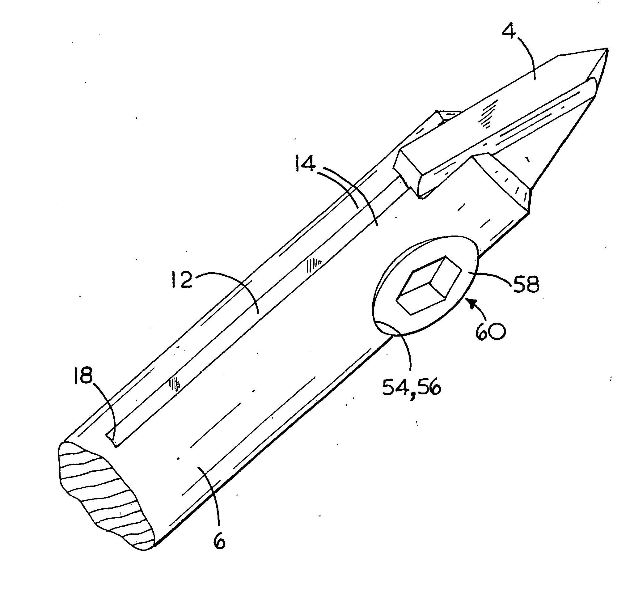
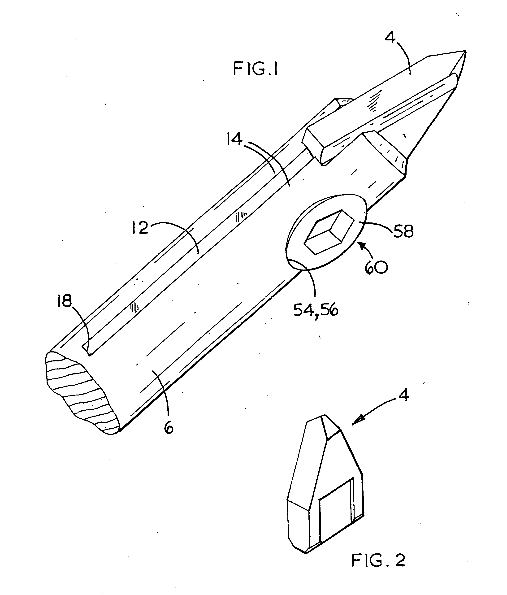
[0032] Referring to FIG. 1, a drill bit 2 is shown for rotary cutting of ceramic material. The drill bit 2 has a cutting plate 4 and an elongate cylindrical shank 6 defining a central longitudinal axis 8 of rotation. One end of the shank 6 engages a chuck of a rotary power drill (not shown). A groove 12 is at the opposite end of the shank 6. The groove 12 seats the cutting plate 4. The groove 12 is flanked by a pair of opposing jaws 14. The cutting plate 4 is removably clamped by the jaws 14 to secure it to the shank 6. The cutting plate 4 is formed from a suitably hard material like, for example, hardened steel or tungsten carbide. In use, the drill bit 2 rotates in the direction of the circular arrow R, as is shown in FIG. 4.

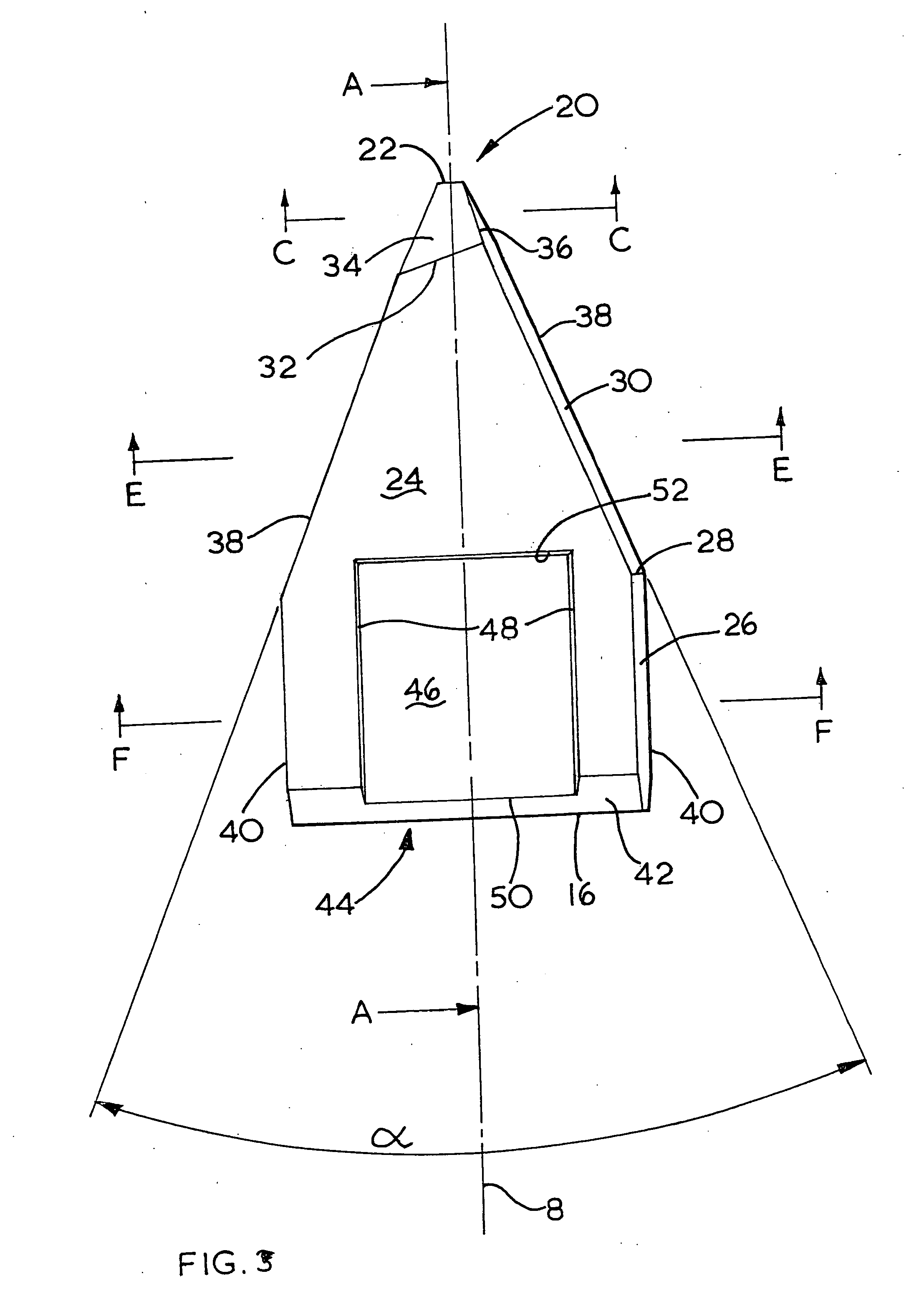
[0033] When viewed in front elevation, as is shown in FIG. 3, the cutting plate 4 is gene...


PUM

PropertyMeasurementUnit
angleaaaaaaaaaa
angleaaaaaaaaaa
angleaaaaaaaaaa

Abstract

A cutting plate (4) has a working end (20) to engage a workpiece and an axis (8) of rotation. A pair of oppositely arranged first faces (34) are inclined axially rearward from the working end (20) in an axial plane intersecting said first faces (34). A pair of second faces (30) are alternately arranged between the first faces (34). The second faces (30) are inclined axially rearward from the working end (20) in an axial plane (37) intersecting the second faces (30), and a pair of axis parallel front faces (24). Each of the front faces (24) is bound on three sides by a respective first face (34) and the pair of second faces (30). Each second face (30) is inclined radially inward from a transitional edge with a respective rotationally leading first face (34) in a plane normal to the axis (8) intersecting the transitional edge with a respective rotationally leading first face (34). Each first face (34) is inclined radially inward from a transitional edge (36) with a respective rotationally leading second face (30) in a plane normal to the axis (8) intersecting the transitional edge (36) with a respective rotationally leading second face (30), as the cutting plate (4) rotates.

Description

CROSS-REFERENCE TO RELATED APPLICATIONS [0001] This application claims priority to Great Britain Patent Application No. 0308287.2 filed Apr. 10, 2003, which application is herein expressly incorporated by reference. FIELD OF THE INVENTION [0002] The present invention relates to a cutting plate for a drill bit and relates particularly, but not exclusively, to a cutting plate for a drill bit for rotary cutting of ceramic tiles. The invention also relates to a drill bit incorporating such a cutting plate. BACKGROUND OF THE INVENTION [0003] Rotary cutting of a ceramic tile presents various difficulties because of the hardness and smoothness of both the glazed protective layer of the tile and the tile substrate material itself. It is known to cut ceramic tiles by initially using a small diameter drill bit to cut a small hole in the protective layer to minimise the possibility of cracking the protective layer and the tile substrate. Next drill bits of successively larger diameters are use...

Claims


Application Information

Patent Timeline
Patent Type & Authority Applications(United States)
IPC IPC(8): B23B51/00B28D1/14
CPCB23B51/00B23B2251/04B28D1/146Y10T408/90993B23B2251/18B23B2251/50Y10T408/9093Y10S408/713
Inventor BINDER, MARCOROMPEL, MARKUSSTOCKBAUER, FRANZ JR.
Owner BLACK & DECKER INC
Learn More