

Blade inlet cooling flow deflector apparatus and method
a deflector and blade technology, applied in the direction of rotor propellers, rotary propellers, propellers, etc., can solve the problems of uneven cooling flow split, excessively difficult to efficiently feed the internal cooling passages of blades, and difficult to achieve high-speed rotating machinery. efficient
- Summary
- Abstract
- Description
- Claims
- Application Information
AI Technical Summary
Benefits of technology
Problems solved by technology
Method used
Image

Examples
Embodiment Construction
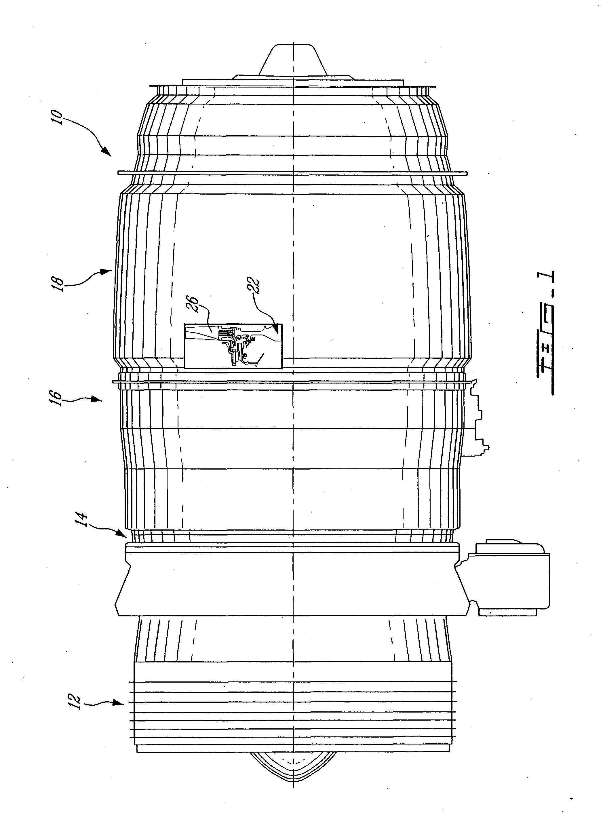
[0025]FIG. 1 illustrates a gas turbine engine 10 generally comprising in serial flow communication a fan 12 through which ambient air is propelled, a multistage compressor 14 for pressurizing the air, a combustor 16 in which the compressed air is mixed with fuel and ignited for generating an annular stream of hot combustion gases, and a turbine 18 for extracting energy from the combustion gases.
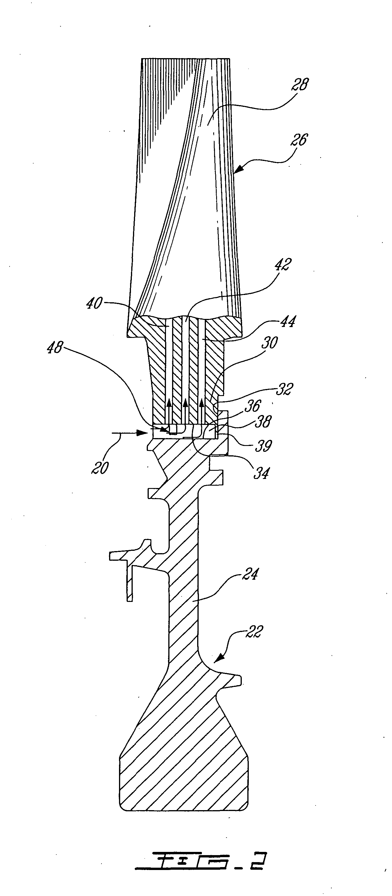
[0026] As depicted by arrows 20 in FIG. 2, a portion of the air coming from the compressor 14 (or any other source of coolant) is provided to the turbine 18 for cooling purposes. The turbine 18 comprises, among others, a rotor 22 having a disc 24 securely mounted to the engine shaft (not shown) linking the turbine 18 to the compressor 14. The disc 24 carries at its periphery a plurality of circumferentially distributed blades, one of which is shown at 26.
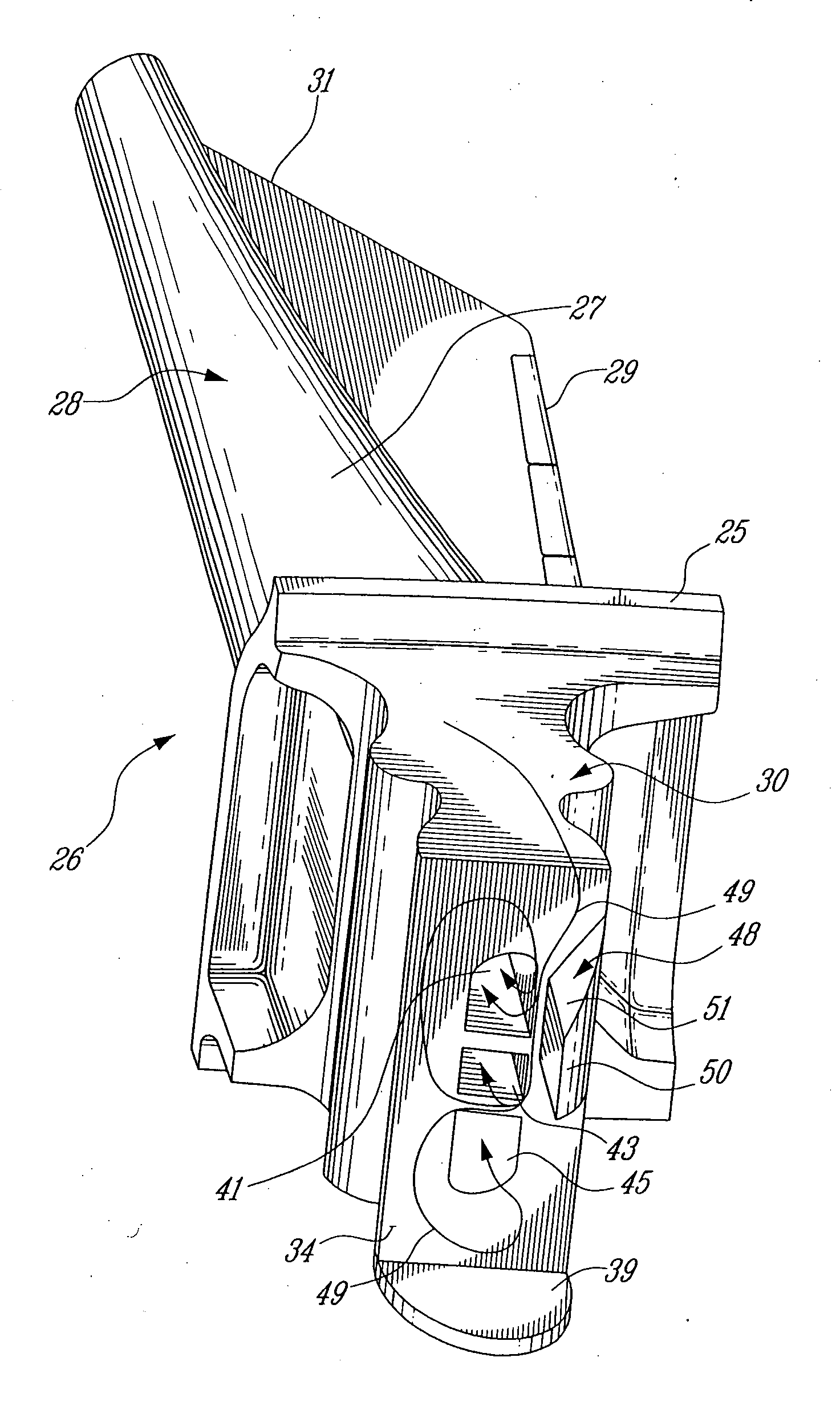
[0027] As shown in FIG. 3, each blade 26 has an airfoil portion 28 having a leading edge 27, a trailing edge 29 and a tip 31. The airfoil ...
PUM
 Abstract
Description
Claims
Application Information