Method and apparatus for controlling fluid movement in a microfluidic system
Inactive Publication Date: 2005-02-03
PETITHORY HENRY
View PDF4 Cites 64 Cited by
Summary
Abstract
Description
Claims
Application Information
AI Technical Summary
This helps you quickly interpret patents by identifying the three key elements:
Problems solved by technology
Method used
Benefits of technology
[0009] A preferred centrifuge has a platform that comprises at least one fluid passage having a shape that increases the time required to move the fluid from one chamber to another over the time required to move the fluid between the same chambers by a passage following the shortest path between the chambers. A preferred centrifuge has a platform that comprises a plurality of chambers and connecting passages such that two fluids are moved to the same chamber. A preferred centrifuge has a platform that comprises at least one chamber has a shape that increases mixing of two fluids entering the chamber. A preferred centrifuge has a platform that comprises a chamber has internal baffles to increase mixing. A preferred centrifuge has a platform that comprises a passage that prevents flow by having a size that prevents flow of a fluid through the passage in the absence of a force applied to the fluid in the direction of the passage. A preferred centrifuge has a platform that comprises a passage that prevents flow by the location of the passage relative to the direction of forces acting on the fluid in the chamber in a fi
Problems solved by technology
However heretofore the art has not taught the use of a simple open channel microfluidic system wherein a specially adapted rotor is used to change orientation of the microfluidic plate when the centrifuge rotor is at rest thereby controlling
Method used
Image
Click on the blue label to locate the original text in one second.
Reading with bidirectional positioning of images and text.
Examples
Embodiment Construction
[0021] Microfluidic devices of the invention may be fabricated from any conventional material. Thermoplastics such as perfluroethylene (such as DuPont's Teflon® brand), polyethylene, polypropylene, methylmethacrylates and polycarbonate, among others, are preferred due to their ease of molding, micromachining and stamping. Alternatively, the devices can be made of or can be made in part of silica, glass, quartz or inert metal.
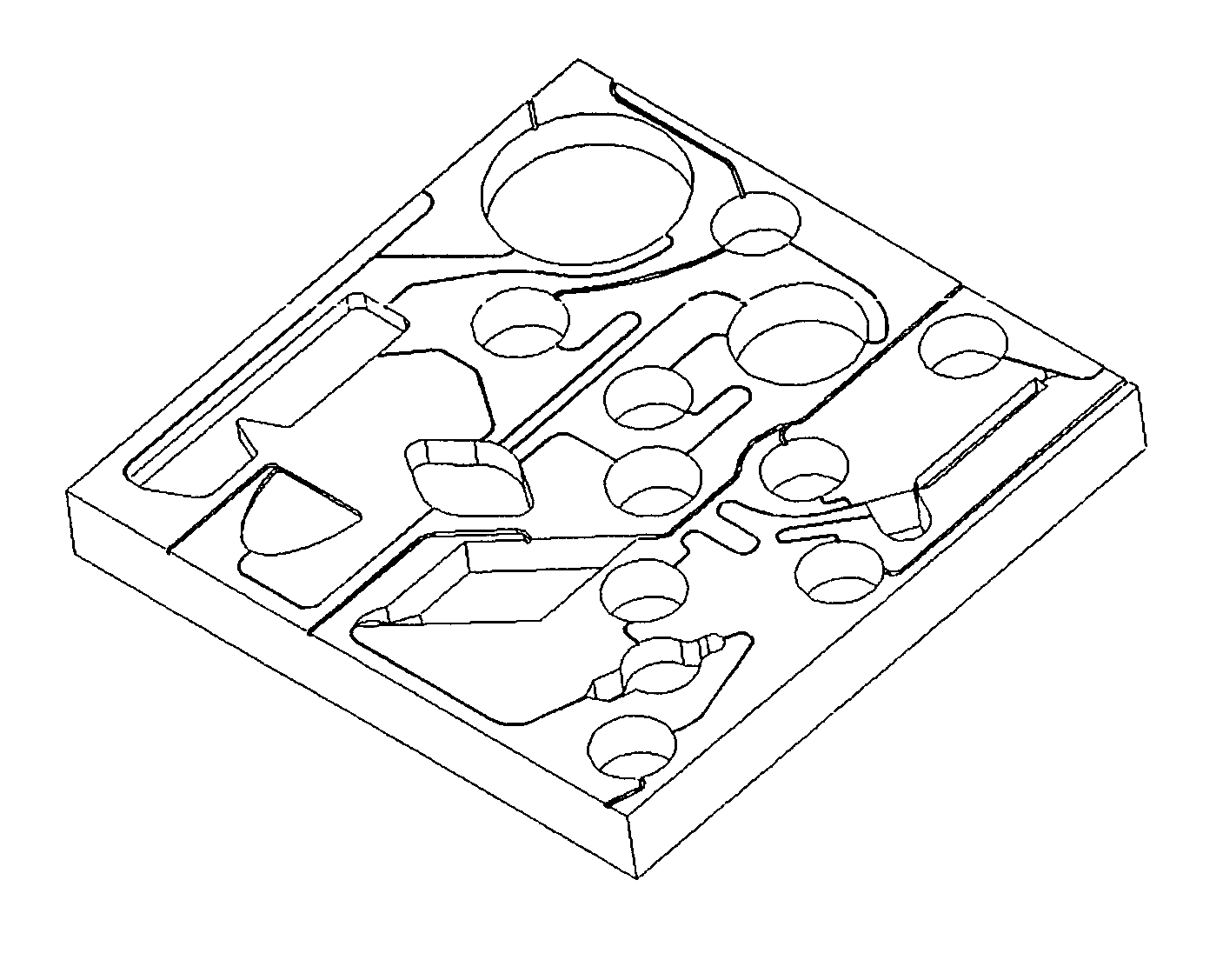
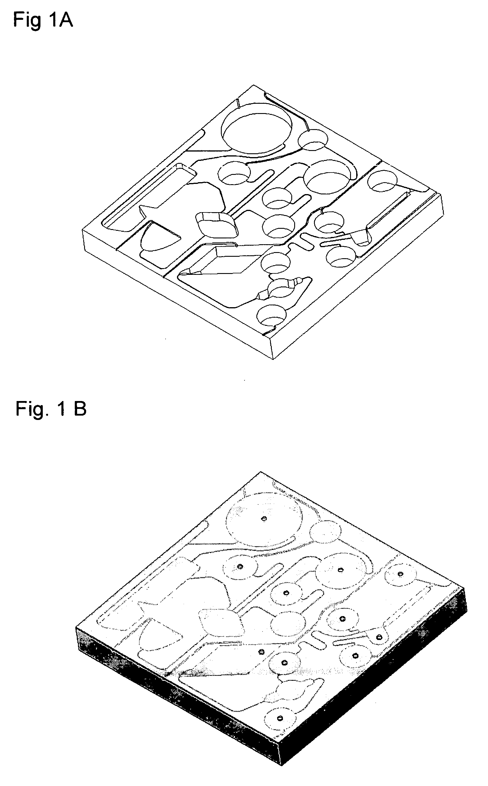
[0022]FIG. 1A illustrates a prototype device used to test the invention. The device was machined from a 43 mm×43 mm×6 mm piece of polyoxymetheylene (Delrin® brand polyacetal available from I.E. DuPont and Co., Wilmington, Del.) and included channels and chambers in various formats to simulate three common laboratory procedures: an immunoassay of blood, cell harvesting / washing, and a “spin column” sample enrichment. In order to conserve space on the platform, chambers for fluid wastes and overflows were omitted from the design and fluids were allowed to exit the...
PUM
Property
Measurement
Unit
Time
aaaaa
aaaaa
Force
aaaaa
aaaaa
Centrifugal force
aaaaa
aaaaa
Abstract
The invention provides a method for moving a fluid sample within an open channel flow device by centrifugal force and specially adapted apparatus for practicing the method of the invention. The inventive method is a mechanically simple method for moving a fluid in a platform by changing the orientation of a platform relative to the direction of applied forces when the centrifuge rotor is at rest in order to move a fluid sequentially through a plurality of chambers, wherein movement of the fluid is controlled by the location or size of the passages connecting chambers relative to the direction of forces acting on the fluid.
Description
RELATED APPLICATIONS [0001] This application is a section 371 national phase application from PCT international application Serial Number PCT / US03 / 09162PCT Filed 24 Mar. 2003., claiming priority from U.S. provisional application Ser. No. 60 / 368,113 filed Mar. 25, 2002, and U.S. application Ser. No. 10 / 396,280. filed 24 Mar. 2003, now abandonedTECHNICAL FIELD [0002] This invention relates to chemical or biological tests and procedures in microfluidic apparatus, and specifically to a microfluidic platform mounted on a centrifuge rotor adapted to carry out chemical, biological or biochemical tests or processes. BACKGROUND OF THE INVENTION [0003] There are numerous systems for carrying out small scale chemical tests or processes. See for example U.S. Pat. Nos. 4,812,294, 4,814,282 4,883,763, 4,776,832, 5,696,233, 5,639,428 and 6,302,134. The devices described therein emphasize manipulation of chemical samples in small platforms wherein fluids are moved from one chamber to another by app...
Claims
Application Information
Patent Timeline
Application Date:The date an application was filed.
Publication Date:The date a patent or application was officially published.
First Publication Date:The earliest publication date of a patent with the same application number.
Issue Date:Publication date of the patent grant document.
PCT Entry Date:The Entry date of PCT National Phase.
Estimated Expiry Date:The statutory expiry date of a patent right according to the Patent Law, and it is the longest term of protection that the patent right can achieve without the termination of the patent right due to other reasons(Term extension factor has been taken into account ).
Invalid Date:Actual expiry date is based on effective date or publication date of legal transaction data of invalid patent.