

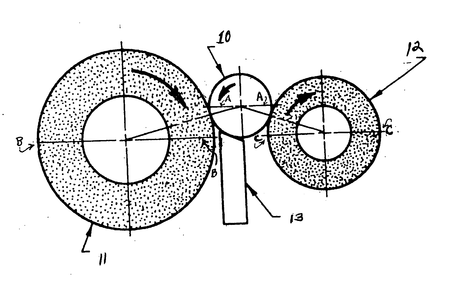
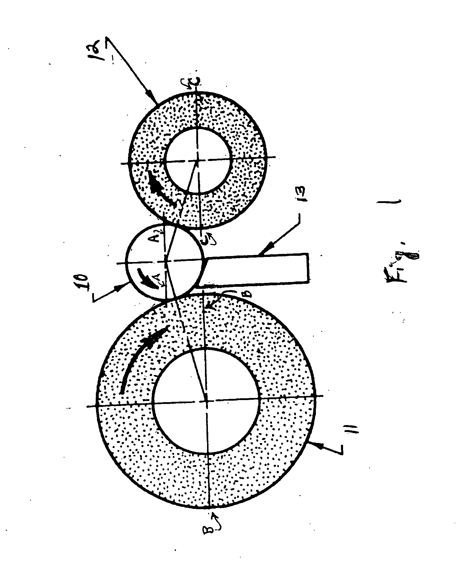
Method of centerless grinding
a centerless grinding and grinding wheel technology, applied in the direction of gear teeth, gear teeth, gear-teeth manufacturing apparatus, etc., can solve the problem of increasing the wear rate of the wheel
- Summary
- Abstract
- Description
- Claims
- Application Information
AI Technical Summary
Benefits of technology
Problems solved by technology
Method used
Image

Examples
example 1
Abrasive Grain / Vitrified Binder Agglomerates
Vitrified binding materials (see Table 1-1, footnotes b and c) were used to make agglomerated abrasive grain. The agglomerates were prepared according to the rotary calcination method described in U.S. Ser. No. 10 / 120,969, Example 1, using the materials described below. The agglomerates were made with 3 wt. % Binder A. The calciner temperature was set at 1250° C., the tube angle was 2.5 degrees and the rotation speed was 5 rpm. The abrasive grain was a fused alumina 38A abrasive grain, 80 grit size, obtained from Saint-Gobain Ceramics & Plastics, Inc., Worcester, Mass., USA.
The vitrified grain agglomerates were tested for loose packing density, relative density and size. Test results are listed in Table 1-1 below. Agglomerates consisted of a plurality of individual abrasive grits (e.g., 2 to 40 grits) bonded together by vitrified binding material at grit to grit contact points, together with visible void areas. The majority of the agg...
PUM
| Property | Measurement | Unit |
|---|---|---|
| speed | aaaaa | aaaaa |
| density | aaaaa | aaaaa |
| density | aaaaa | aaaaa |
Abstract
Description
Claims
Application Information