Pulsating Stent Graft

a stent and stent technology, applied in the field of pulsating stent graft, can solve the problems of affecting the treatment effect of patients, the risk of open surgery being carried out, and the consequences of large artery slippage can be very serious

Active Publication Date: 2005-02-03
ARKUSZ MIKE +1
View PDF12 Cites 41 Cited by
  • Summary
  • Abstract
  • Description
  • Claims
  • Application Information

AI Technical Summary

Problems solved by technology

Open surgical procedures however often carry substantial risk to the patient.
One of the more serious problems that the physicians using this technology have to cope with relates to the fact that the intraluminally implanted graft is less securely attached to the vessel wall and can therefore slip away from the intended location.
Consequences of such slippage in the case of a large artery can be very serious.

Method used


Image

  • Pulsating Stent Graft
  • Pulsating Stent Graft
  • Pulsating Stent Graft

Examples


Embodiment Construction

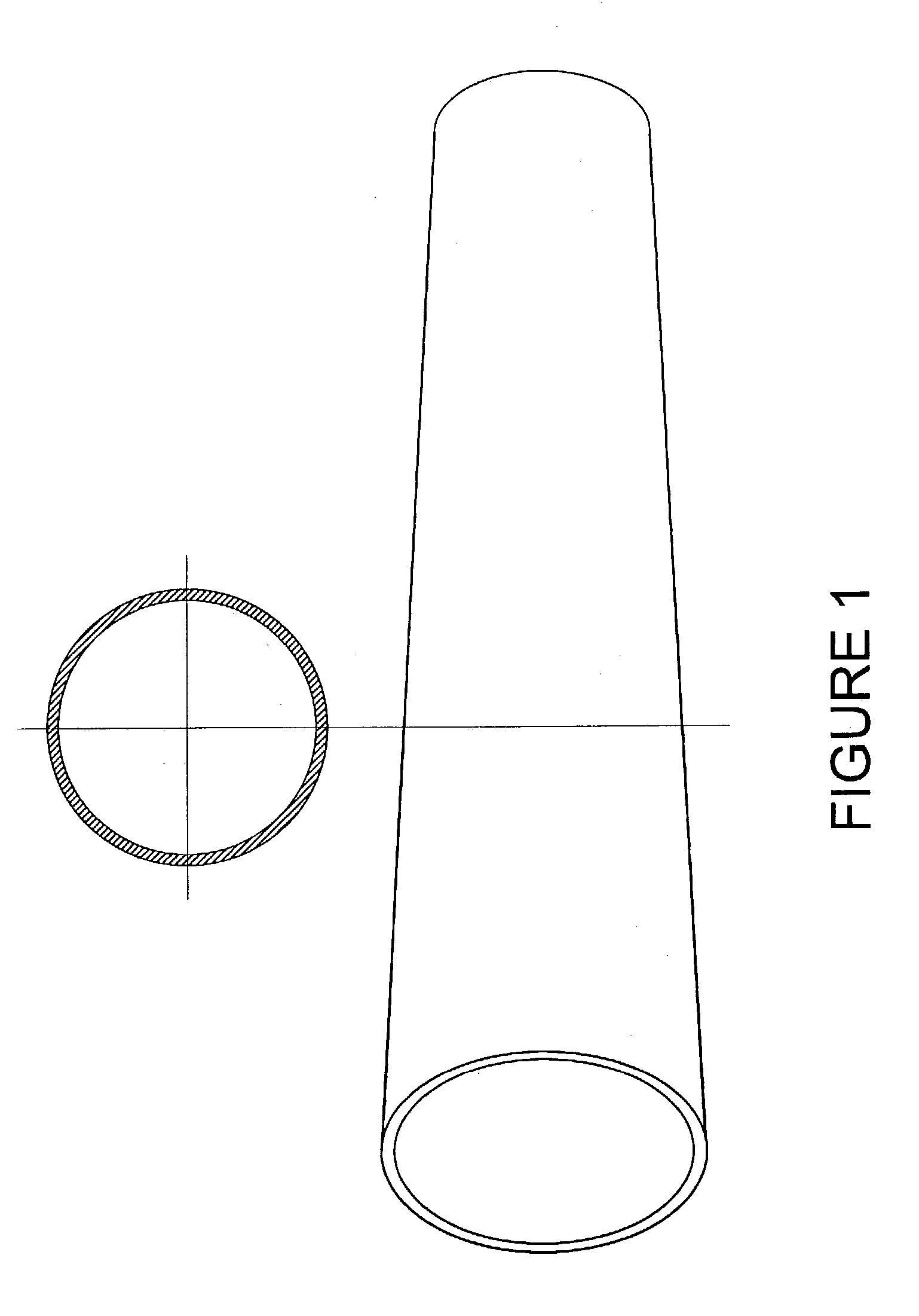
[0004]FIG. 1 shows a typical intraluminal non-bifurcated stent graft in its expanded form. Typically such a graft is comprised of a stent or a series of stents with an internal or external covering, or both, the said covering made of PTFE film or similar material. To accommodate for the change in the size of the artery the proximal end of the stent graft has a larger diameter than the distal end. Often the proximal end of the stent graft is also equipped with elements like hooks or an uncovered stent for attaching the body of the device to the arterial wall. Bifurcated versions of the stent graft would branch off to the vessels in the arterial tree.

[0005] Typically the stent graft tapers off in a uniform fashion from the larger proximal opening to the smaller distal opening. The cross-section of the lumen of the stent graft remains substantially circular throughout the length of the stent graft body within constrains allowed by the structural elements of the stent.
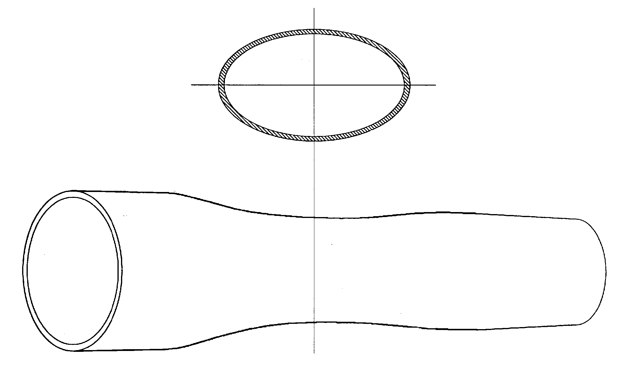
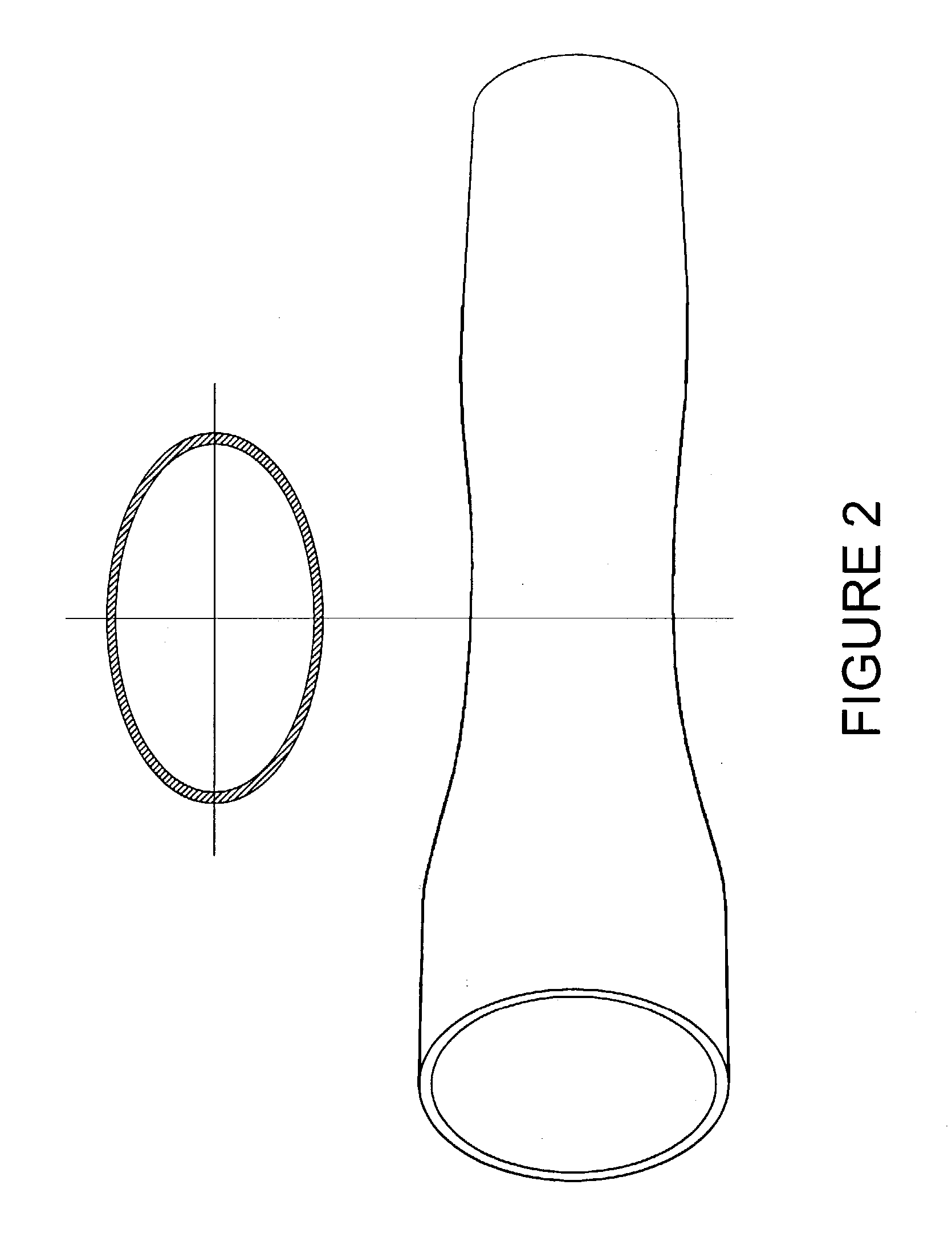
[0006]FIG. 2 des...


PUM


Abstract

A tubular vascular stent graft with passively pulsating midsection where the difference between the cross-sectional areas of the lumen under the systolic and diastolic pressures after the implantation is 10% or more. The pulsating stent graft accumulates blood during the systolic pressure wave thus lowering the peak value of the tugging force at the proximal attachment site.

Description

BACKGROUND OF INVENTION [0001] Tubular flexible grafts are currently a standard tool for repairing failures in the vascular system. During open surgical procedures such grafts are securely sewn onto the vessel in a manner that prevents detachment or leakage. Open surgical procedures however often carry substantial risk to the patient. In recent years a new technology has emerged which seeks to deliver grafts supported by stents through the use of catheter like devices introduced into the vascular system at a convenient location and then guided remotely to the site where the stent graft is implanted. [0002] One of the more serious problems that the physicians using this technology have to cope with relates to the fact that the intraluminally implanted graft is less securely attached to the vessel wall and can therefore slip away from the intended location. Consequences of such slippage in the case of a large artery can be very serious. Various methods have been developed to counter t...

Claims


Application Information

Patent Timeline
Patent Type & Authority Applications(United States)
IPC IPC(8): A61F2/06
CPCA61F2230/0078A61F2/07
Inventor ARKUSZ, MIKEARKUSZ, TOM
Owner ARKUSZ MIKE
Why Eureka
Try Eureka