Exhaust control apparatus of internal combustion engine and exhaust gas flow amount estimating method

Inactive Publication Date: 2005-02-10
TOYOTA JIDOSHA KK +1
View PDF9 Cites 93 Cited by
  • Summary
  • Abstract
  • Description
  • Claims
  • Application Information

AI Technical Summary

Benefits of technology

[0019] According to the exhaust gas flow amount estimating method, in the case of supplying the fuel to the exhaust purifying device in each exhaust passage, it is possible to estimate the flow amount of the exhaust gas of each exhaust passage by utilizing the change of the air fuel ratio detected by the air fuel ratio detecting device. Further, it is not necessary to execute the procedure of estimating the flow amount of the exhaust gas every time when the estimation of the exhaust gas flow amount of e

Problems solved by technology

In the V-type engine as mentioned above, a dispersion is generated in the exhaust gas flow amount introduced to each of the exhaust passages due to a difference in volume charging efficiency between the cylinder groups, a difference in flow amount characteristic of an EGR apparatus and the like, and some kind or another disadvantages maybe generated owing to the matter.
In this case, an opti

Method used


Image

  • Exhaust control apparatus of internal combustion engine and exhaust gas flow amount estimating method
  • Exhaust control apparatus of internal combustion engine and exhaust gas flow amount estimating method
  • Exhaust control apparatus of internal combustion engine and exhaust gas flow amount estimating method

Examples


first embodiment

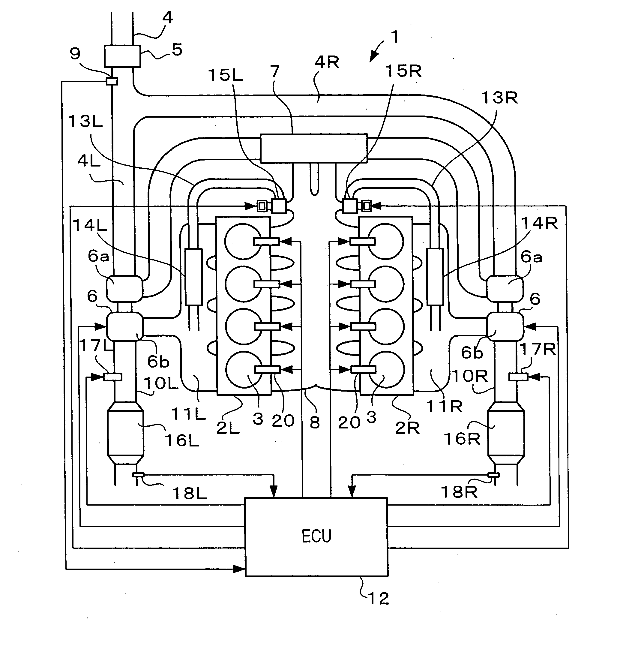
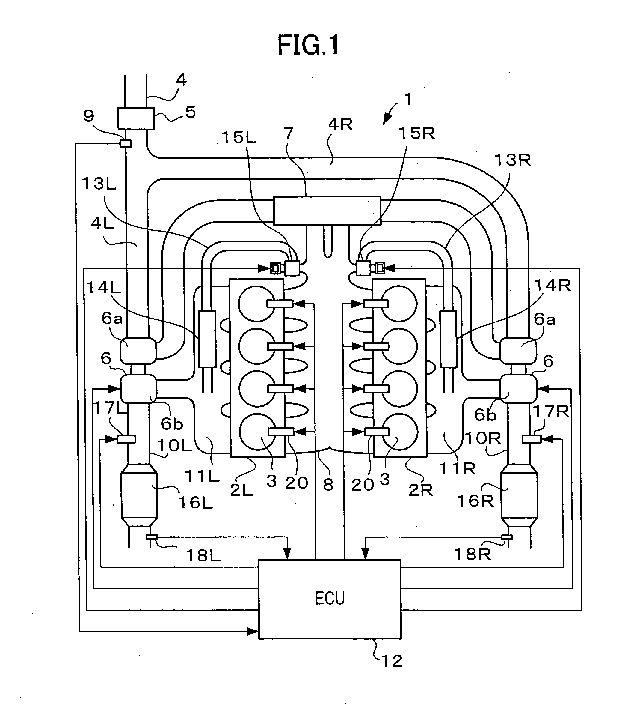
[0029]FIG. 1 shows an internal combustion engine for being mounted to a vehicle according to the first embodiment of the present invention. In this embodiment, the internal combustion engine is structured as a V-type 8-cylinder diesel engine 1 in which four cylinders 3 are provided in each of left and right banks 2L and 2R. One cylinder group is structured by the cylinders 3 in the left bank 2L, and another cylinder group is structured by the cylinders 3 in the right bank 2R.

[0030] An intake passage 4 for conducting intake air to each of the cylinders 3 is separated into branch passages 4L and 4R per the banks in a downstream side of an air cleaner 5, and a compressor portion 6a of a turbocharger 6 is arranged in each of the branch passages 4L and 4R. Each of the branch passages 4L and 4R passes through an inter cooler 7 in a downstream side of the compressor portion 6a, and is connected to a common intake manifold (a common intake passage) 8 constituting a part of the intake passa...

second embodiment

[0044] Next, a description will be given of the second embodiment according to the present invention with reference to FIGS. 4 to 9. FIG. 4 shows an internal combustion engine to which an exhaust control apparatus according to the second embodiment is applied, and the same reference numerals are attached to the same portions as those in FIG. 1. The engine 1 according to this embodiment is different from the engine 1 in FIG. 1 in a point that the left and right EGR passages 13L and 13 Rare connected to each other via a communication passage 13C. The other portions are the same.

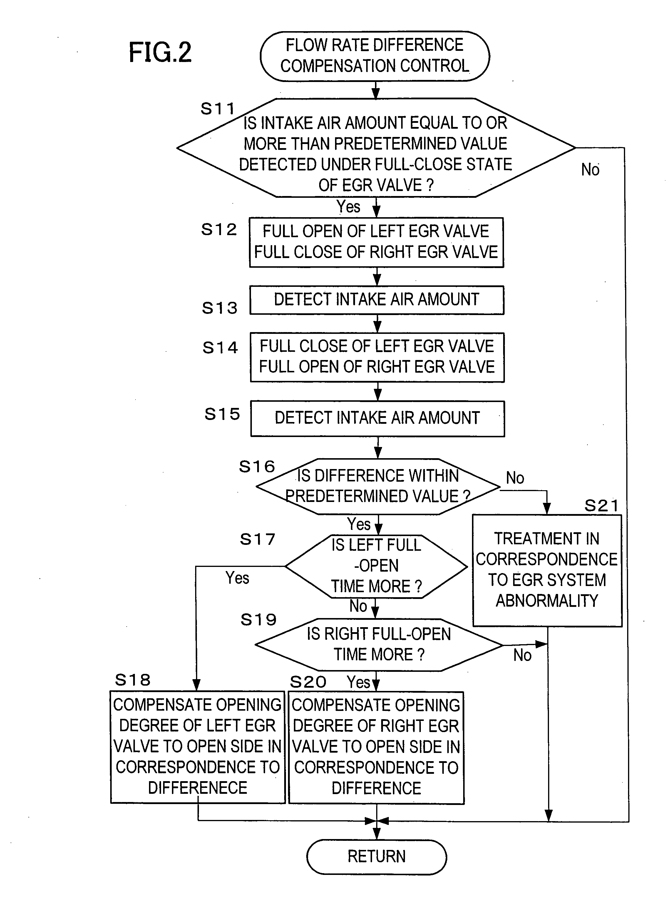
[0045] The ECU 12 executes a control for reducing the exhaust gas flow amount difference in the filters 16L and 16R of the exhaust passages 10L and 10R in the same manner as that of the first embodiment, however, a procedure thereof is different from the first embodiment. A description will be given below of a calculation of the exhaust gas flow amount difference and an operation for reducing the exhaust gas f...


PUM


Abstract

An exhaust control apparatus applied to an internal combustion engine in which intake sides of a plurality of cylinder groups are connected to a common intake passage and exhaust sides thereof are connected to different exhaust passages, comprises an exhaust gas flow amount adjusting device for causing a flow amount of exhaust gas, which is discharged through each of the exhaust passages of the cylinder groups, to be changed, an exhaust gas flow amount difference estimating device for estimating a difference in an exhaust gas flow amount between the exhaust passages of the cylinder groups, and an exhaust gas flow amount control device for controlling the exhaust gas flow amount adjusting device so as to reduce the estimated difference in the exhaust gas flow amount.

Description

BACKGROUND OF THE INVENTION [0001] 1. Field of the Invention [0002] The present invention relates to an exhaust control apparatus which can cancel an exhaust gas flow amount difference between cylinder groups of an internal combustion engine, and an exhaust gas flow rate estimating method which can be used therefor. [0003] 2. Description of the Related Art [0004] As an internal combustion engine having a structure in which cylinder groups are connected to different exhaust passages, there has been, for example, known a V-type engine in which a cylinder group is structured in each of banks and each of the cylinder groups is connected to the different exhaust passage. Further, as an exhaust control apparatus applied to this kind of V-type engine, there has been known an exhaust control apparatus which controls an ignition timing of each bank such that each of catalysts reaches a temperature suitable for reproduction by canceling a dispersion in temperature between the catalysts at the...

Claims


Application Information

Patent Timeline
IPC IPC(8): F01N3/02F01N3/025F01N3/035F01N3/08F01N3/20F01N13/08F02B3/06F02B29/04F02B37/007F02B75/18F02B75/22F02D13/02F02D21/08F02D23/00F02D23/02F02D41/00F02D41/14F02D41/18F02D41/22F02D41/36F02D45/00F02M25/07
CPCF01N3/0253F01N13/011F01N3/0814F01N3/0821F01N3/0842F01N3/0885F01N9/002F01N2610/03F02B3/06F02B29/0406F02B37/007F02B75/22F02B2075/1832F02B2275/14F02D23/02F02D41/0072F02D41/0082F02D41/0087F02D41/1443F02D41/1446F02D41/1448F02D41/18F02D41/22F02D2200/0402F02D2200/0804F02M25/0711F02M25/0732F02M25/0744F02M25/0748Y02T10/144Y02T10/47F01N3/035F02M26/08F02M26/24F02M26/38F02M26/42Y02T10/12Y02T10/40
Inventor FUKUMA, TAKAOTAKAHASHI, YOSHIYUKI
Owner TOYOTA JIDOSHA KK
Why Eureka
Try Eureka