Vehicle air-conditioner

Inactive Publication Date: 2005-02-10
CALSONIC KANSEI CORP
View PDF11 Cites 25 Cited by
  • Summary
  • Abstract
  • Description
  • Claims
  • Application Information

AI Technical Summary

Benefits of technology

[0004] In the vehicle air-conditioner, generally, a proper refrigerant amount during the cooling operation mode is more than a proper refrigerant amount during the heating operation mode. However, an allowable range of the proper refrigerant amount during the heating operation

Problems solved by technology

However, an allowable range of the proper refrigerant amount during the heating operation mode is narrow.
When

Method used


Image

  • Vehicle air-conditioner
  • Vehicle air-conditioner
  • Vehicle air-conditioner

Examples


first embodiment

[0026] First Embodiment

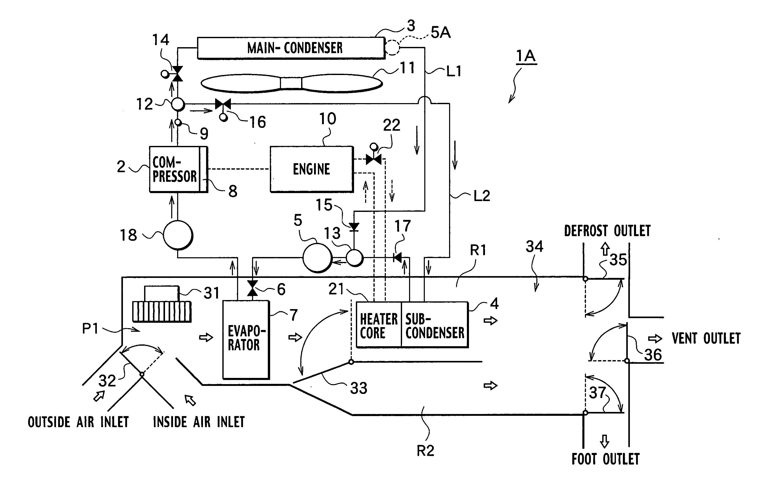
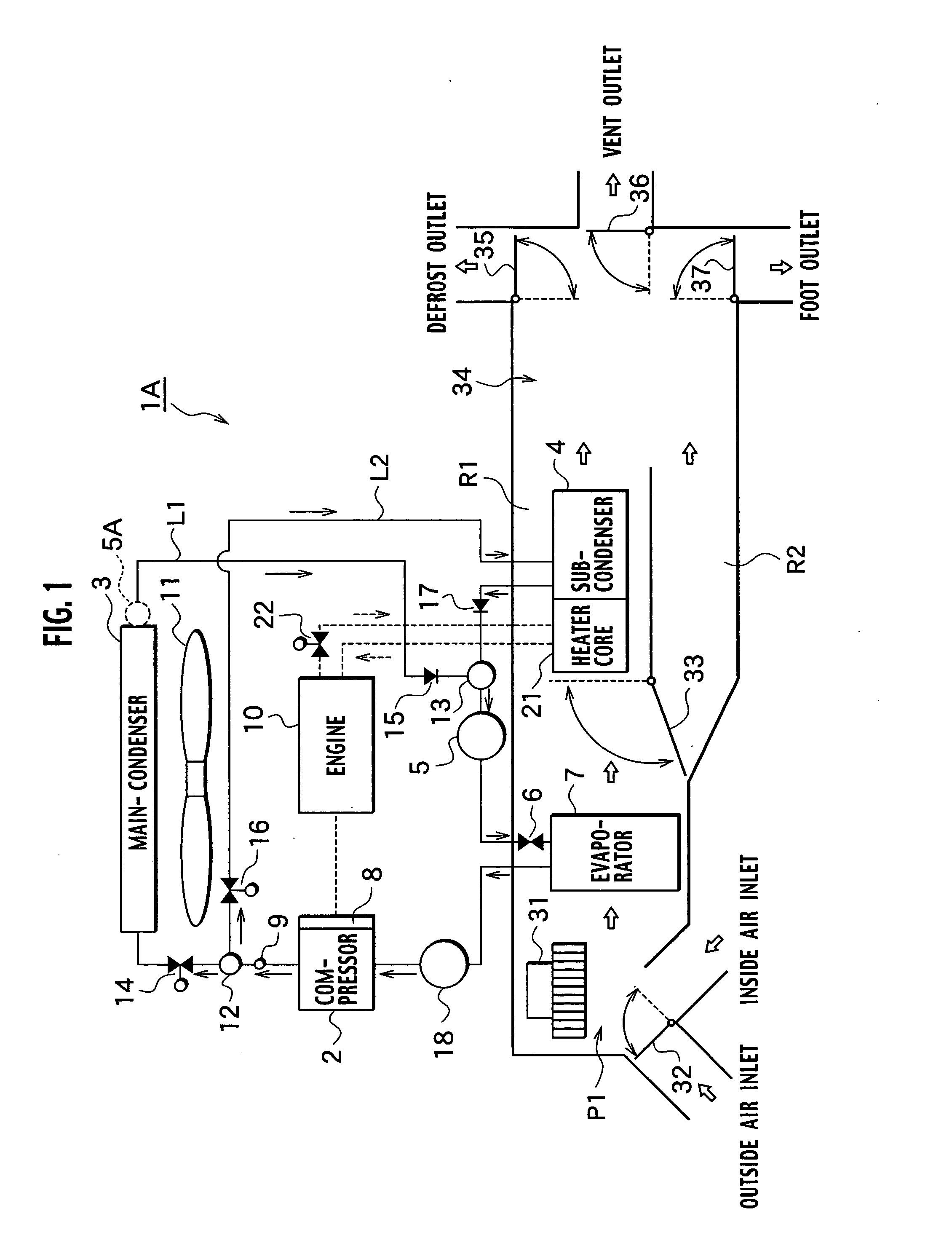
[0027] A vehicle air-conditioner 1A (hereinafter, “air-conditioner”) includes a refrigerating cycle that performs heat-exchange between refrigerant and air, with the refrigerant circulated therein. The air-conditioner 1A includes a hot water line which allows engine-cooling water (cooling water for vehicle driving system) heated by exhaust heat of an engine. The hot water line performs heat-exchange between the engine cooling water and air.

[0028] The refrigerating cycle includes a compressor 2. The refrigerating cycle includes a main condenser 3 serving as a within-vehicle condenser and a sub-condenser 4 serving as a within-vehicle condenser downstream of the compressor 2. The refrigerating cycle includes a liquid tank 5, an expansion valve 6 and an evaporator 7 downstream of both the condensers 3, 4. These members are in fluid communication with and connected to one another through piping members. Refrigerant is imparted with kinetic energy from the compress...

second embodiment

[0076] Second Embodiment

[0077] With reference to FIG. 5, an air-conditioner 1B has a liquid tank 5 disposed between the sub-condenser 4 and the three-way valve 13. The air-conditioner 1B includes a liquid tank 5A just after a main condenser 3 or use a main condenser integrated with a liquid tank. The structure allows use of a tank with a volume suitable for each condenser and prevents unnecessary liquid refrigerant from entering in each condenser. This advantageously ensures a desired cooling / heating performance.

[0078] This structure allows use of sub-cool condenser. The sub-cool condenser is used to improve a cooling performance for cooling liquid refrigerant. In view of fluctuation of refrigerant at a charging time thereof or leakage of refrigerant after charged, the main condenser, liquid tank and sub-cool tank are disposed in this order from an upstream side so as to allow for slight increase / decrease in a refrigerant amount. That is, the refrigerant is discharged from the main...


PUM


Abstract

An air-conditioner includes a compressor. The air-conditioner includes a first condenser positioned outside of a vehicle-compartment. The air-conditioner includes an expansion valve. The air-conditioner includes an evaporator positioned within an air-passage in the vehicle-compartment for introducing inside or outside air. The air-conditioner includes a second condenser positioned on downstream side of the evaporator in the air-passage. The vehicle air-conditioner has a heating operation mode and a cooling operation mode switchable therebetween. The evaporator and the compressor have an accumulator provided therebetween. The expansion valve opens, while refrigerant has temperatures at 0° C. or less on outlet side of the evaporator.

Description

CROSS-REFERENCE TO RELATED APPLICATIONS [0001] This application is based upon and claims the benefit of priority from Japanese Patent Application No. 2003-286034 filed on Aug. 4, 2004; the entire contents of which are incorporated herein by reference. BACKGROUND OF THE INVENTION [0002] The present invention relates to a vehicle air-conditioner, where switching between a cooling operation mode and a heating operation mode is performed by selectively using an outside-vehicle condenser and a within-vehicle condenser. [0003] A patent document of Japanese Patent Application Laid-open No. 2002-211234 discloses the above type of vehicle air-conditioner. The vehicle air-conditioner includes a compressor. The air-conditioner includes an outside-vehicle condenser disposed outside of a vehicle compartment. The air-conditioner includes an expansion valve. The air-conditioner includes an evaporator disposed in a within-vehicle air passage introduced with outside and inside air. The air-condition...

Claims


Application Information

Patent Timeline
IPC IPC(8): B60H1/00F25B6/00F25B41/04B60H1/32
CPCB60H1/00921B60H1/3213B60H2001/3263F25B2400/0403F25B6/00F25B41/04F25B2327/001B60H2001/3285F25B41/20F25B41/24
Inventor HATAKEYAMA, JUN
Owner CALSONIC KANSEI CORP
Why Eureka
Try Eureka