
Method and apparatus for manufacturing compressed earthen blocks

a technology of earthen blocks and compressed materials, applied in the field of building materials, can solve the problems of difficult to achieve the transmission of even compressive forces through a large volume of such materials, large energy consumption, and heavy and expensive equipment, and achieve the effect of high dimensional accuracy and homogeneity

Inactive Publication Date: 2005-02-10
DYNABLOC TECH
View PDF32 Cites 14 Cited by
  • Summary
  • Abstract
  • Description
  • Claims
  • Application Information

AI Technical Summary

Benefits of technology

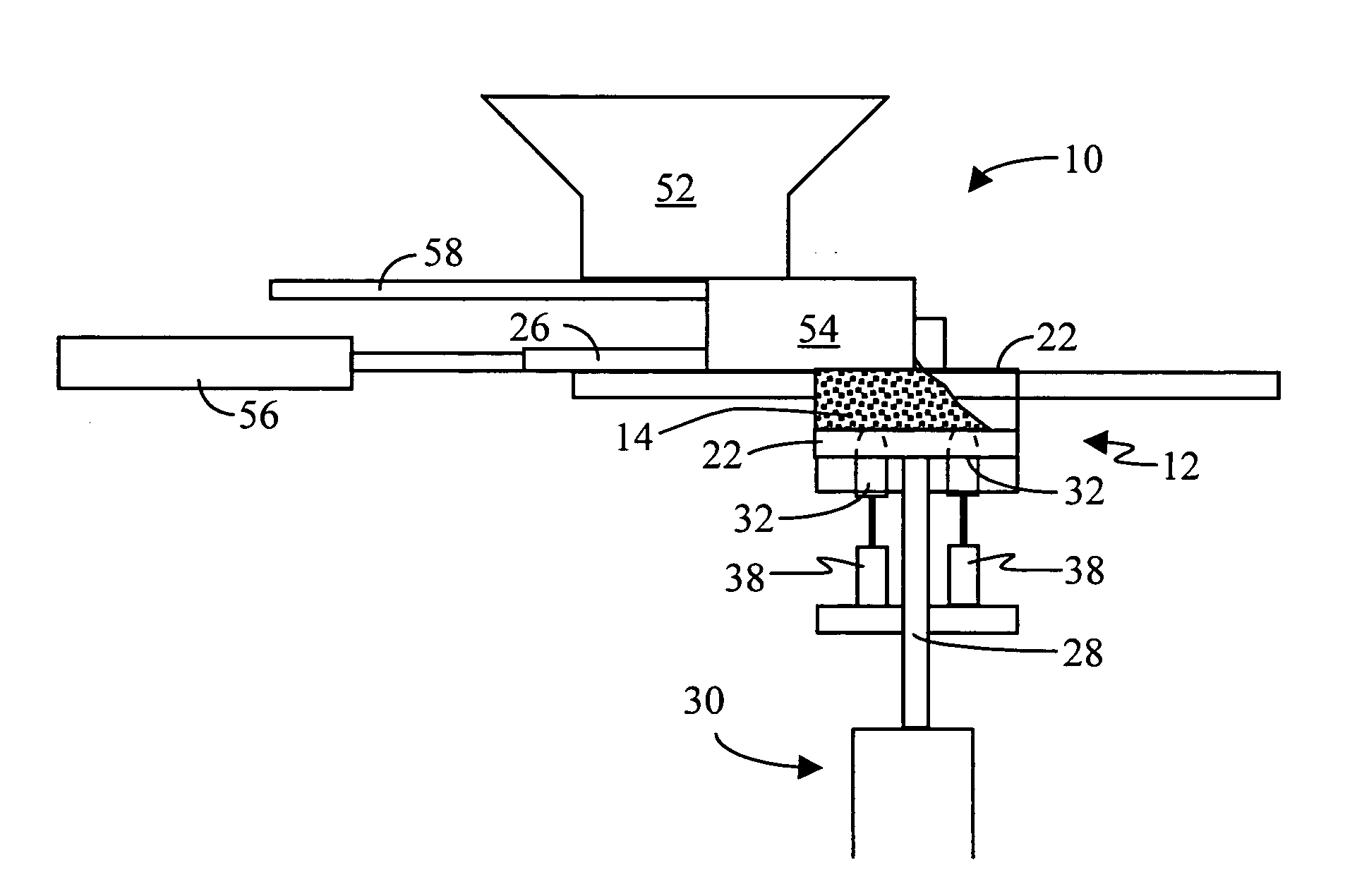
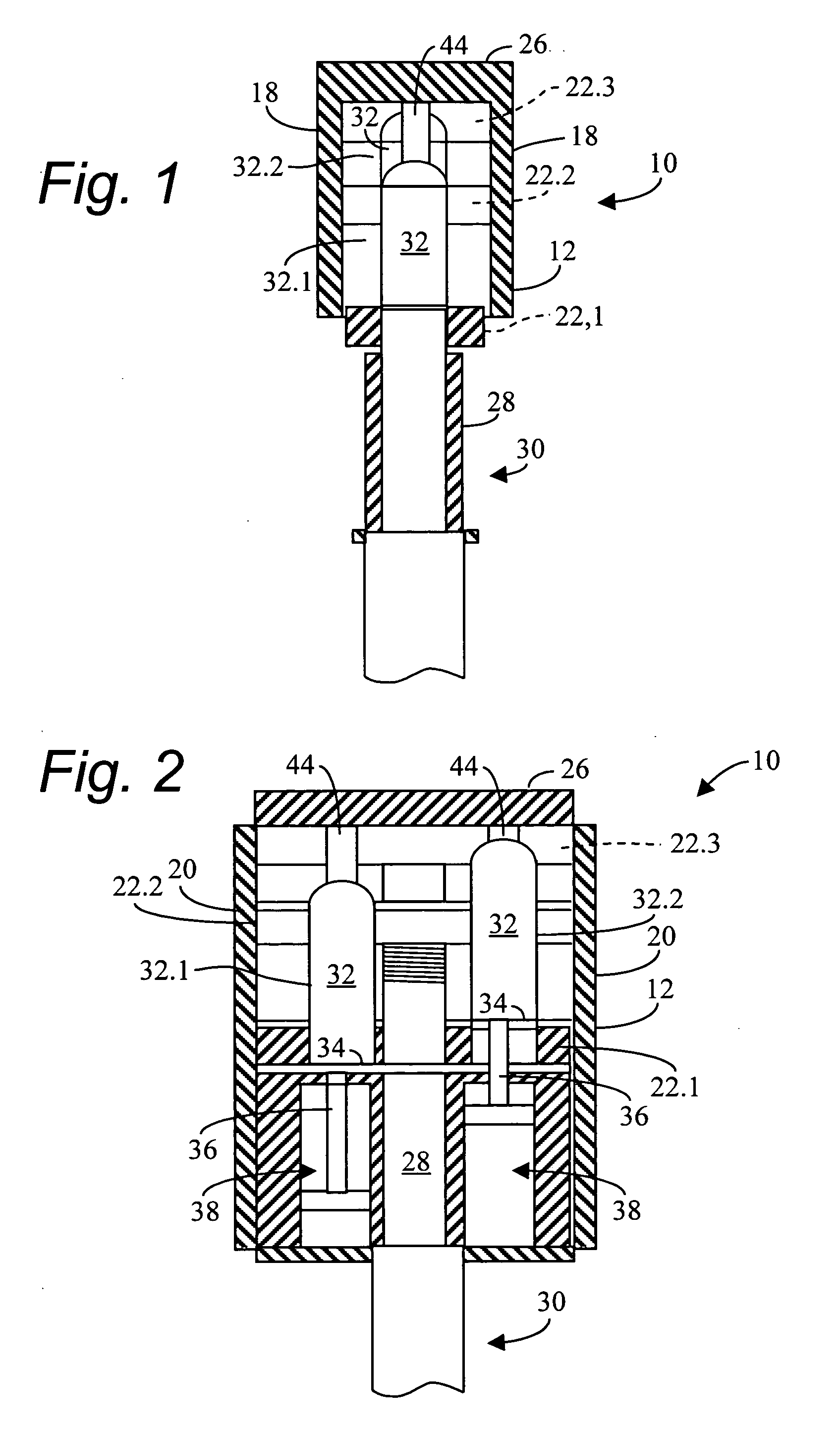
It is an object of the invention to provide a block making apparatus and method for making compressed earthen building blocks which will, at least partially, alleviate the abovementioned problems, enabling the manufacture of building blocks of high dimensional accuracy and homogeneity, as well as having dimensional consistency.
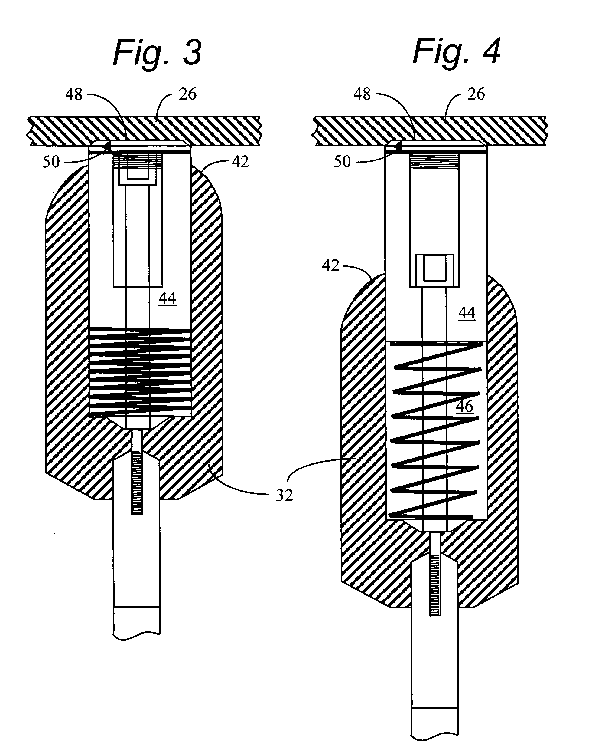
As a second stage of manufacture, the at least one dog is urged into the block material in the compression chamber under the action of a predetermined force. In this step, the outer dimensions of the block are not altered, but the block material is significantly compressed, enhancing the overall compression of the block, as well as the homogeneity of the compression.
Commonly, the compression chamber has a parallelepiped shape. However, other shapes may be envisioned. In fact, mold plates of different profiles can be readily replaced, enabling compressed earthen building blocks of various profiles to be made, including special purpose and interlocking blocks.

Problems solved by technology

Another problem encountered in the manufacture of compressed earthen building blocks is the achievement of homogeneity throughout the building block.
This has proved a challenge.
The raw material used in the manufacture of such blocks is of a particulate nature and the transmission of even compressive forces throughout a large volume of such material is difficult to achieve.
In order to achieve acceptable compression at the distal end of the chamber, it is necessary to apply large ram forces to the raw material, thereby necessitating the use of heavy and expensive equipment and the consumption of relatively large amounts of energy.
It has also been found that even where the requisite even distribution of pressure is achieved within the raw material in the compression chamber, it is difficult to achieve dimensional consistency of the finished block.

Method used


Image

  • Method and apparatus for manufacturing compressed earthen blocks
  • Method and apparatus for manufacturing compressed earthen blocks
  • Method and apparatus for manufacturing compressed earthen blocks

Examples


first embodiment

a calibration unit is shown in FIG. 27. The calibration cylinder 2710 is filled with a known volume of raw material 14, such as a complete calibration cylinder 2710 full. A weight 2720 has been sized to provide a pressure in the calibration cylinder 2710 equal to that which will be experienced in the compression chamber of the compressed earthen building block apparatus 10. The weight 2720 apples a force at the end of a lever arm 2730 to which a piston 2740 is operatively, pivotally attached. The lower end of the piston 2740 engages the raw materials 14 in the calibration cylinder 2710. After the lever arm 2730 and weight 2720 have ceased their descent, the sample has achieved its full compression as it would in the compression chamber 12 of the compressed earthen building block apparatus 10. The amount of compression may be read off a scale 2750 which may be graduated into units representing either v2 or Av.

second embodiment

a calibration unit is shown in FIG. 28. In this embodiment, disc springs 2900 as detailed in FIG. 29 are used to apply the force to the raw materials 14. Again, a cylinder 2800 is filled with raw materials 14, in this case, from the bottom of the cylinder 2810 as shown in FIG. 28. A force mechanism 2820 is threaded down over the cylinder 2810 via threads 2830. The force mechanism 2820 comprises a piston 2840 that engages the raw materials 14, and a plurality of disc springs 2900. An example of a force-displacement spring characteristics plot is shown in FIG. 30. In this embodiment, an operator must keep track of both the compression amount via a lower scale 2850 that moves with the piston 2840 and an upper scale 2860 that is stationary with respect to a lower knob 2870. In this way, the compression of the springs 2900 may be calculated by subtracting the length of the lower scale 2850 from that of the upper scale 2860. Based on the stress-strain relationship shown in FIG. 30, the sp...


PUM

PropertyMeasurementUnit
sizeaaaaaaaaaa
pressureaaaaaaaaaa
volumeaaaaaaaaaa

Abstract

A machine and method for producing dimensionally consistent compressed earthen blocks under consistent and uniform pressures is disclosed. The approximately rectangular shaped block is formed in a rectangular parallelepiped shaped chamber having given dimensions. A plate forms one wall of this chamber and has the mobility required to compress the earth within the chamber. At the termination of compression, this plate is located at a predetermined location. A dog is forced into the compressed earthen block after the compression plate has ceased which effectively reduces the internal volume of the chamber. The dog is forced in under a known and consistent pressure. When a block is formed of less material, the terminal point for the dog will be further into the block than when the same-size block is made of more material. Additional aspects include a calibration unit for determining a volume of raw material to load into the compression chamber; and a hydraulic cylinder able to actuate two coaxial rams independently.

Description

STATEMENT REGARDING FEDERALLY SPONSORED RESEARCH OR DEVELOPMENT Not applicable. REFERENCE TO MICROFICHE APPENDIX Not applicable. BACKGROUND OF THE INVENTION 1. Field of the Invention This invention relates to building material. More particularly, the invention relates to a method and apparatus for making building blocks. In particular, the invention relates to an apparatus and method for the manufacture of compressed-earth building blocks. Further, the invention relates particularly to the manufacture of compressed stabilized building blocks of soil or earth that have a good degree of dimensional accuracy and uniformity or density using a primary and secondary compression method. 2. Background Art Many forms of building block are known for use in construction of building structures. One form of such building block comprises particulate earth or soil which is compressed in a mold to form the building block. Such building blocks are sometimes known by the names “soil blocks,”“ea...

Claims


Application Information

Patent Timeline
Patent Type & Authority Applications(United States)
IPC IPC(8): B28B1/44B28B3/02B28B13/02B28B17/00B29C43/04B30B11/04B30B15/30E04C
CPCB28B1/44B28B3/027B28B17/0081B30B11/04B30B15/304B28B13/023
Inventor BURLOW, GEORGEBYLEVELDT, GERTHUTCHINS, JULIAN BRYANRYERSON, RICHARD A.HALEY, THOMAS R.
Owner DYNABLOC TECH
Learn More