Method and device for producing a film made of a thermoplastic material

a thermoplastic material and film technology, applied in the direction of dough shaping, food shaping, other domestic articles, etc., can solve the problems of negative effect on the visual appearance of the finished film, damage to the film bubble, and corresponding involuntary production stoppage, so as to increase the stiffness of the rear wall, increase the sturdiness, and ensure the effect of dimensional stability

Inactive Publication Date: 2005-02-10
REIFENHAUSER GMBH & CO MASCHFAB
View PDF10 Cites 9 Cited by
  • Summary
  • Abstract
  • Description
  • Claims
  • Application Information

AI Technical Summary

Benefits of technology

[0014] In accordance with one embodiment of this invention, a laminar air cushion is created between the film guidance elements of the calibrating arrangement and / or the flattening device, and an extraordinarily uniform support of the film bubble occurs, which assures high product quality, while dependably avoiding any contact at all between the film guidance element and the film bubble. Thus it is possible with the method in accordance with this invention to provide a film web with great adhesive effect on the basis of composite EVA structures, composite PIB structures, composite structures with ionomers in PE-LLD films, and the like.
[0017] According to this invention, one advantage is an extraordinarily low consumption of air and little operating noise. It is thus possible when charging the film guidance elements with an air flow of 0.5 to 4 bar to operate them with an air flow or throughput in the direction toward the film bubble corresponding only to 0.2 l / min dm2 at 0.5 bar, and to 1.6 l / min dm2 at 4 bar, wherein with even this low air throughput a contactless guidance is assured because of the formation of a laminar air cushion.
[0019] It is within the scope of this invention for an air-permeable microporous layer, which faces the film bubble and is used for letting the air exit, to allow the air flow supplied to the film guidance elements to exit through a multitude of narrowest and closely adjoining micropores in such a fine distribution that an extremely uniform and constant air cushion is formed, so that the film bubble can be dependably calibrated and / or flattened without being touched, even if it develops a large tendency toward tackiness and large adhesive forces.
[0027] Then the front wall is placed on the circumferential wall and the intermediate strips and is welded along the circumferential wall so as to be air-tight, for example by laser welding. The intermediate strips can also be connected with the front wall by individual spot welds in order to increase sturdiness during the subsequent charging with a compressed air flow.
[0028] Finally, the intermediate strips also increase the stiffness of the rear wall, so that an extremely compact and dimensionally stable housing results. According to this invention, when producing the housing from a metallic material, consisting of a 2 mm thick rear wall, from which circumferential walls and intermediate strips of a height of 1 mm can be obtained by 1 mm deep milled areas, and a 2 mm thick front wall with air outlet openings, it is possible to obtain a two-part housing which offers a surprisingly good and uniform air distribution and formation of the desired air cushion.
[0029] Thus, a uniform homogeneous air cushion between the film bubble and the surface of the film guiding element facing it is created, having a size proportional to the interior pressure in the air chamber of the housing. Also, by dividing the air chamber by intermediate strips into partial chambers communicating with each other, there are no partial air cushion differences over the entire surface of the film guidance element facing the film bubble, so that an extraordinarily uniform contactless guidance and calibration, or flattening, of the film bubble is achieved.

Problems solved by technology

However, this contact of the calibrating arrangement with the film, which has not yet been completely cooled and solidified in the area of the calibrating arrangement, is disadvantageous, for example when producing highly transparent or tacky film, because respective running marks can form on the film with this contact, which then has a negative effect on the visual appearance of the finished film.
In case of tacky films, a blockage of the calibrating arrangement might even occur, which afterwards results in damage to the film bubble and a corresponding involuntary production stoppage.
However, the cost outlay for an apparatus with high-output blowers, air conduits, as well as an appropriate control technology, is very great, and there is a problem with too strong air flows causing undesirable temperature effects on the film bubble might occur, which negatively affect the quality of the film obtained.
However, the known device is employed for guiding a web of already great stability through a coating device.

Method used


Image

  • Method and device for producing a film made of a thermoplastic material
  • Method and device for producing a film made of a thermoplastic material
  • Method and device for producing a film made of a thermoplastic material

Examples


Embodiment Construction

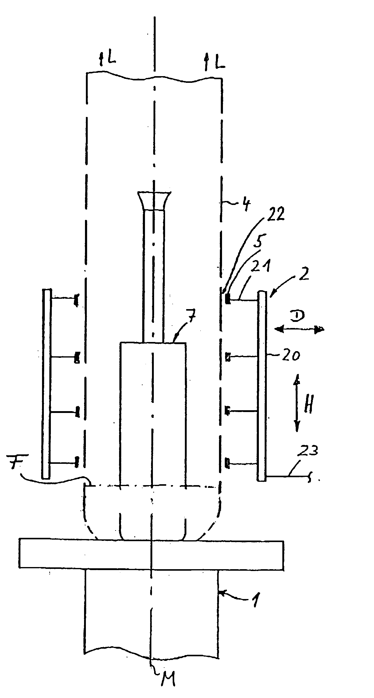
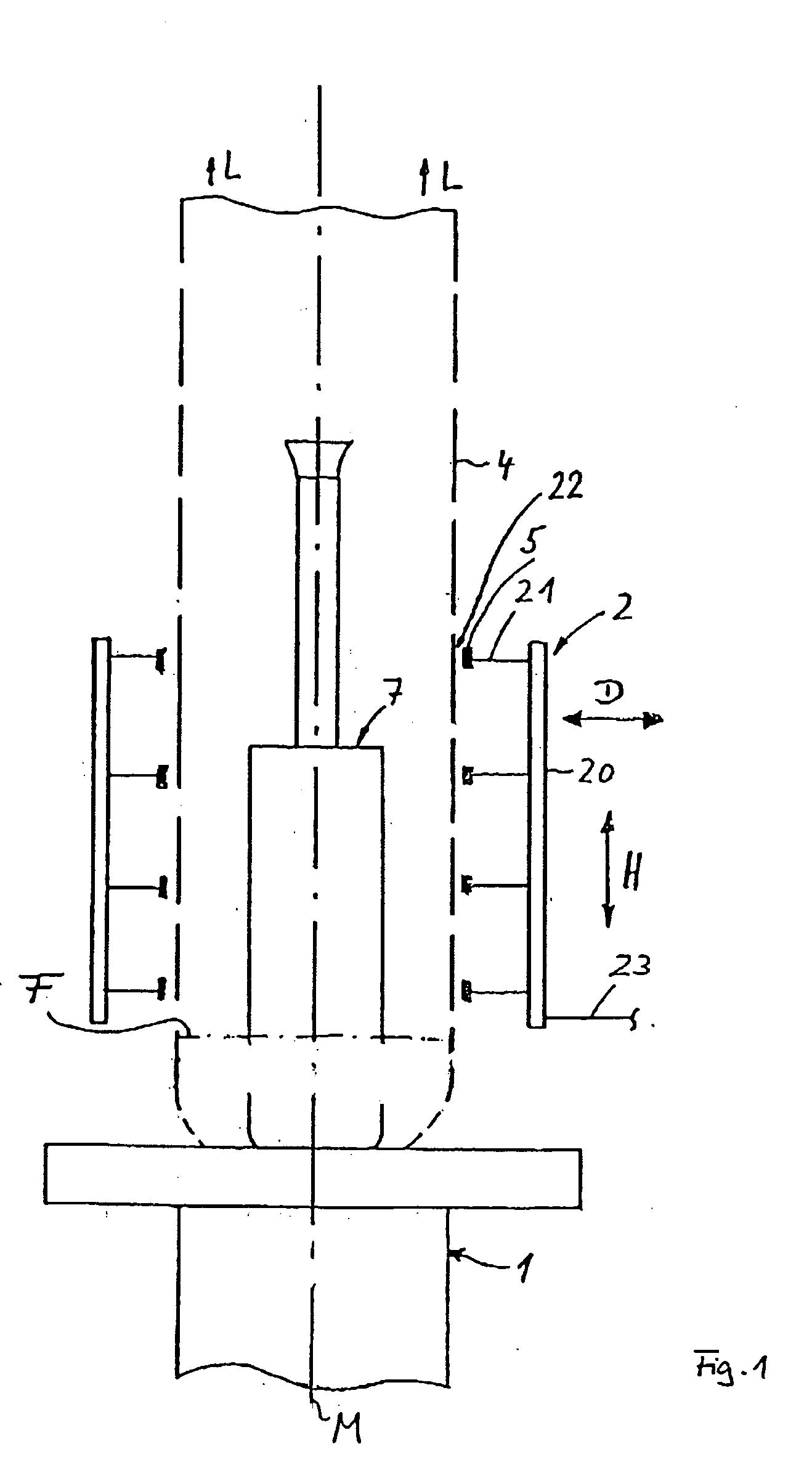
[0042] The device for producing a film made of a thermoplastic material represented in FIG. 1 comprises a blow head 1, not represented in significant detail, which is charged in a known manner with a molten thermoplastic material from an extruder, not visible here. In a thermoplastic state, the plastic material exits the blow head 1 through a ring-shaped outlet opening at the top and is immediately blown into a film bubble 4 and moved vertically away toward the top in the direction of the arrow L. Therefore this film bubble 4 has a circular cross section with a center axis M.

[0043] Directly following its exit from the blow head 1, the plastic material forming the film bubble 4 is still in the thermoplastic state because of its high temperature, but is rapidly cooled to below its solidification temperature, because of which the film bubble 4 is slowly changed into a stable state. The transition between the thermoplastic and the solidified state of the film bubble 4 is identified by ...


PUM

PropertyMeasurementUnit
pore sizeaaaaaaaaaa
thicknessaaaaaaaaaa
pore sizeaaaaaaaaaa

Abstract

A method and a device for producing a film made of a thermoplastic material, wherein a plastic melt is blown up into a film bubble and is shaped into a desired film by a calibrating arrangement, and a downstream arranged flattening device. For providing as contactless as possible a guidance, calibration and flattening, film guidance elements are used with a laminar uniform air cushion between the film guidance element and the surface of the film bubble, without contact between the surface of the film bubble and the film guidance element.

Description

BACKGROUND OF THE INVENTION [0001] 1. Field of the Invention [0002] This invention relates to a method for producing a film made of a thermoplastic material, wherein a melt of a plastic material exits from a blow head supplied by at least one extruder, while forming a film bubble, and then the film bubble passes through a calibrating arrangement, in which it is calibrated to a predeterminable diameter, as well as afterwards is flattened into a film web in a flattening device, and then is rolled up, for example. This invention also relates to a device for producing a film made of a thermoplastic material, having at least one extruder with a blow head for the emergence of a film bubble from the plastic material, a calibrating arrangement acting on the exterior of the film bubble, and a flattening device for the film bubble arranged downstream of the calibrating arrangement, wherein the calibrating arrangement and / or the flattening device have film guidance elements, which can be charg...

Claims


Application Information

Patent Timeline
Patent Type & Authority Applications(United States)
IPC IPC(8): B29C48/10B29C48/90B29C48/92B29C55/28
CPCB29C47/0026B29C47/8835B29C47/92B29C55/28B29C47/903B29C48/10B29C48/913B29C48/90B29C48/903B29C48/908
Inventor WEDELL, EIKEMEYER, HELMUT
Owner REIFENHAUSER GMBH & CO MASCHFAB
Why Eureka
Try Eureka