Motor generator

a motor generator and motor technology, applied in the direction of synchronous generators with multiple outputs, hybrid vehicles, battery/fuel cell control arrangements, etc., can solve the problems of increasing the physical size of the motor generator, increasing the cost of associated equipment, and increasing the mounting space. , to achieve the effect of low cost, improved utilization of interior space, and low cos

Inactive Publication Date: 2005-02-10
PANASONIC CORP
View PDF8 Cites 42 Cited by
  • Summary
  • Abstract
  • Description
  • Claims
  • Application Information

AI Technical Summary

Benefits of technology

Furthermore, by constructing an electric vehicle using a motor generator of the present invention, the requirement seen in conventional electric vehicles of needing to provide two types of motor generator for the high voltage and low voltage systems, or needing to provide a separate DC-DC converter in a motor generator that generates only one kind of voltage during regeneration, is eliminated, and consequently a compact and low cost electric vehicle driving system is constructed, and accordingly, a low cost electric vehicle that allows better utilization of the interior space of the vehicle is provided.

Problems solved by technology

Accordingly, problems arise in that more mounting space is required, and in that the associated costs increase.
If the motor generator is configured with a two winding field winding system, a problem occurs in that when winding the windings that are to provide power for the vehicle, the physical size of the motor generator becomes extremely large, and it cannot be installed in a vehicle.
In addition, another problem arises in that because a field winding system is used, it is difficult to control the respective windings at the same time.

Method used


Image

  • Motor generator
  • Motor generator
  • Motor generator

Examples


first embodiment

(First Embodiment)

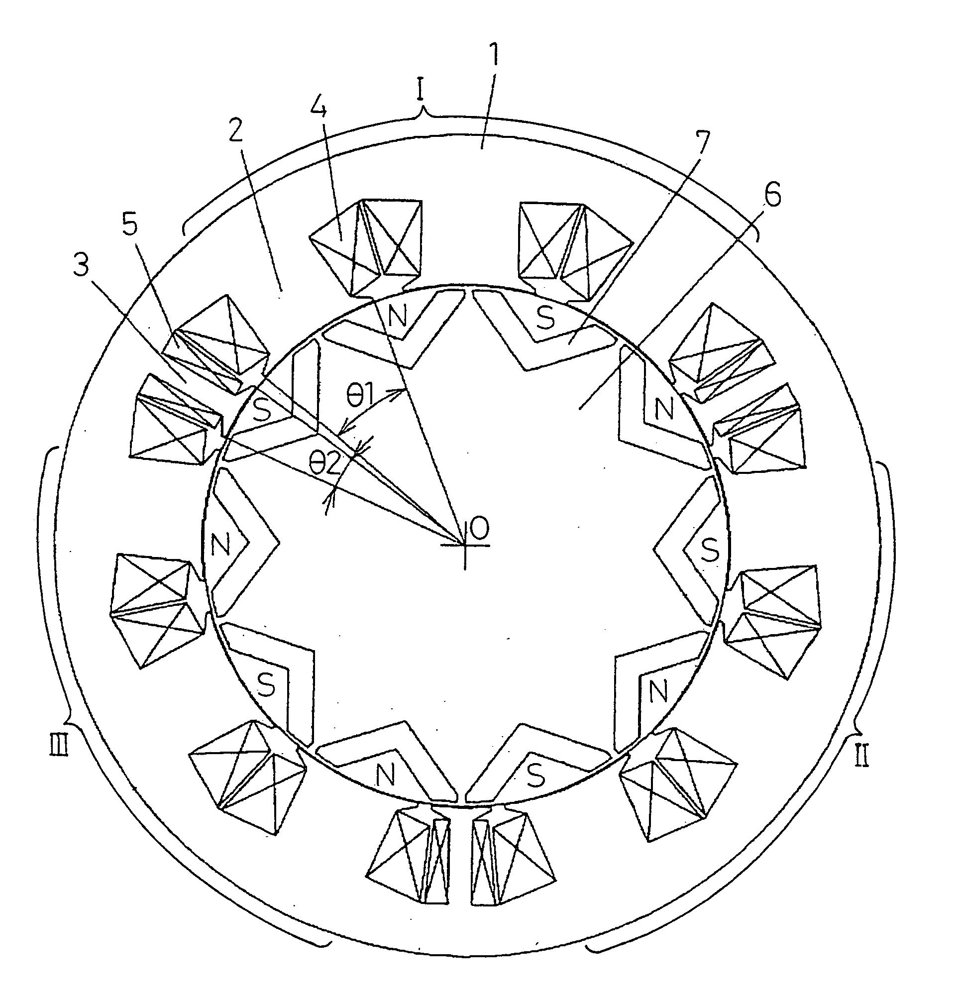
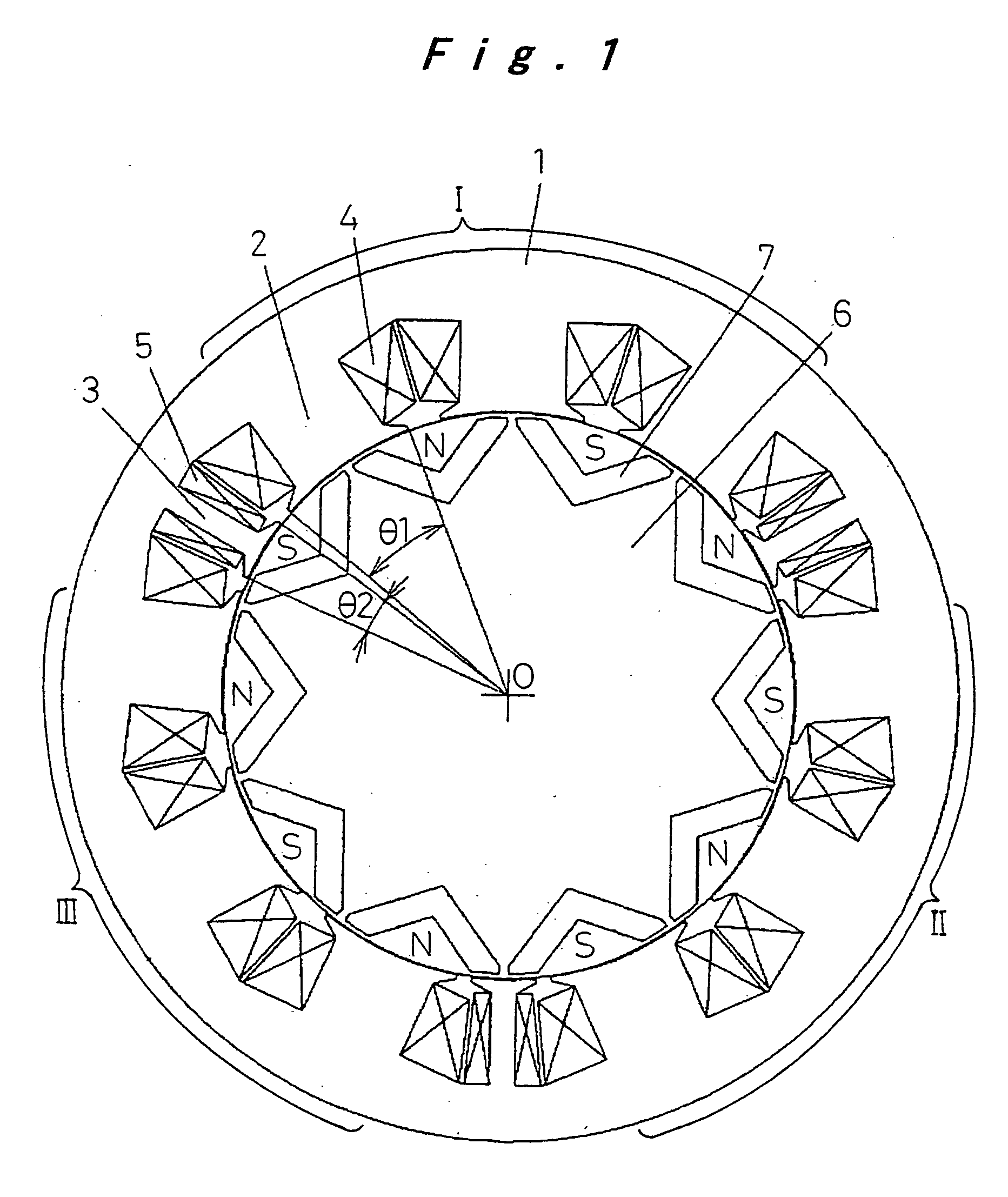
FIG. 1 through FIG. 3 are figures describing a motor generator according to a first embodiment of the present invention, wherein FIG. 1 is a cross-sectional view showing the main elements of a motor along a cross section perpendicular to the central rotational axis, FIG. 2 is a development view describing the winding direction of the windings on the teeth of the first winding groups, and FIG. 3 is a connection diagram showing the state of the connections between the first and second winding groups.

In FIG. 1, a stator core 1, formed from laminated electromagnetic steel plate, is equipped with teeth 2 around which first winding groups 4 are wound, and teeth 3 around which second winding groups 5 are wound. On the other hand, permanent magnets 7 are embedded in a rotor core 6 formed from laminated electromagnetic steel plate, thereby forming a rotor, and are arranged about the center of rotation 0 in a freely rotatable manner, leaving a slight gap between the perman...

second embodiment

(Second Embodiment)

FIG. 5 and FIG. 6 are figures for describing a motor generator according to a second embodiment of the present invention, wherein FIG. 5 is a schematic cross-sectional view of the stator core and the rotor which opposes the inside peripheral surface of the core, along a surface perpendicular to the central rotational axis, and FIG. 6 is a partially enlarged view describing the shape of the teeth which constitute the stator core.

As shown in FIG. 5, a stator core 31 comprises first teeth 32 wound with first winding groups 34, and second teeth 33 wound with second winding groups 35, in the same manner as the first embodiment described above. There are a total of nine first teeth 32 around which the first windings 34 are wound, which are divided into three groups, group I to which U phase voltage is applied, group II to which V phase voltage is applied, and group III to which W phase voltage is applied, and the second teeth 33 around which are wound the second windi...

third embodiment

(Third Embodiment)

FIG. 7A through FIG. 7C are figures for describing a motor according to a third embodiment of the present invention, and are schematic top plan views showing the stator core.

As shown in FIG. 7A, a stator core 51 comprises first teeth 52 wound with first winding groups 54, and second teeth 53 wound with second winding groups 55, in the same manner as for the first embodiment described above. There are a total of nine first teeth 52 around which the first windings 54 are wound, which are divided into three groups, namely group I to which U phase voltage is applied, group II to which V phase voltage is applied, and group III to which W phase voltage is applied, and the second teeth 53 around which are wound the second windings 55 are provided between the groups I, II, and III. Furthermore, in the same manner as for the first embodiment described above, the winding direction of the first winding groups 54 which are wound around the first teeth 52 in the groups I, II,...


PUM


Abstract

A permanent magnet embedded type concentrated winding motor generator, wherein of the mechanically and electrically independent first and second winding groups (4, 5), the plurality of first teeth (2) wound with the first winding groups (4) are divided into three groups (I, II, III) for example, and the winding directions of the windings of adjacent first teeth (2) within the same group (I, II, III) are opposite. Furthermore, one second tooth (3) wound with a second winding group (5) with a different winding specification from the first winding groups (4) is provided between each of the groups (I, II, III). Accordingly, the relative sizes of the generated voltages in the first winding groups (4) and the second winding groups (5) differ each other, allowing the realization of a compact and low cost construction capable of charging two different electric potentials from a single unit, which also enables a reduction in distortion of the waveform of the counter electromotive force, a reduction in iron loss, and an improvement in the efficiency of the motor, and enables the efficient charging of power sources with two different electric potentials.

Description

TECHNICAL FIELD The present invention relates to a motor generator, suitable for an electric vehicle such as a PEV (Pure Electric Vehicle), a HEV (Hybrid Electric Vehicle), or a FCEV (Fuel Cell Electric Vehicle) BACKGROUND ART Conventionally, a hybrid electric vehicle that has an engine and an electric motor as the drive section comprises two types of battery, namely a high voltage battery for driving the electric motor, and an auxiliary low voltage battery for lamps and audio systems and the like. The batteries installed in the vehicle are constructed so that, taking maintenance into consideration, the batteries are charged by a motor generator installed in the vehicle. The construction of a conventional hybrid electric vehicle is shown in FIG. 16. The reference numeral 8 indicates an engine and the reference numeral 9 indicates an electric motor, and power is transmitted from the engine or the electric motor, or from both the engine and the electric motor, to the tires via a po...

Claims


Application Information

Patent Timeline
Patent Type & Authority Applications(United States)
IPC IPC(8): B60K6/26B60K6/48H02K21/16H02K21/48
CPCB60K6/26B60K6/48Y02T10/6221H02K21/48H02K21/16B60L2220/54B60L50/15B60L58/20Y02T10/62Y02T10/64Y02T10/70Y02T10/7072H02K3/18
Inventor KADOYA, NAOYUKIKONDO, YASUHIROTAMAKI, SATOSHI
Owner PANASONIC CORP
Why Eureka
Try Eureka