Analog implementation of spread spectrum frequency modulation in a programmable phase locked loop (PLL) system

a phase lock loop and analog implementation technology, applied in the field of electronic circuits, can solve the problems of reducing the frequency of current modulation, adding expensive and heavy shielding, and using current modulation, so as to reduce high frequency spurs, improve flexibility of modulation, and easily change the spread mode

Inactive Publication Date: 2005-02-10
ALTERA CORP
View PDF12 Cites 14 Cited by
  • Summary
  • Abstract
  • Description
  • Claims
  • Application Information

AI Technical Summary

Benefits of technology

[0009] The present invention uses an analog approach to modulate the control voltage in a phase locked loop. One aspect of the analog approach of the present invention, unlike the existing digital approach, provides a more controlled modulation without having to resort to resetting counters to specific predetermined values. Thus, the analog approach de-couples the counters from the modulation, providing a more flexible modulation scheme. One aspect of the spread spectrum modulator of th

Problems solved by technology

In some existing systems, this is accomplished by adding expensive and heavy shielding.
As noted above, the shielding technique is expensive and physically heavy.
There are a number of disadvantages of using current modulation.
One,

Method used


Image

  • Analog implementation of spread spectrum frequency modulation in a programmable phase locked loop (PLL) system
  • Analog implementation of spread spectrum frequency modulation in a programmable phase locked loop (PLL) system
  • Analog implementation of spread spectrum frequency modulation in a programmable phase locked loop (PLL) system

Examples


Embodiment Construction

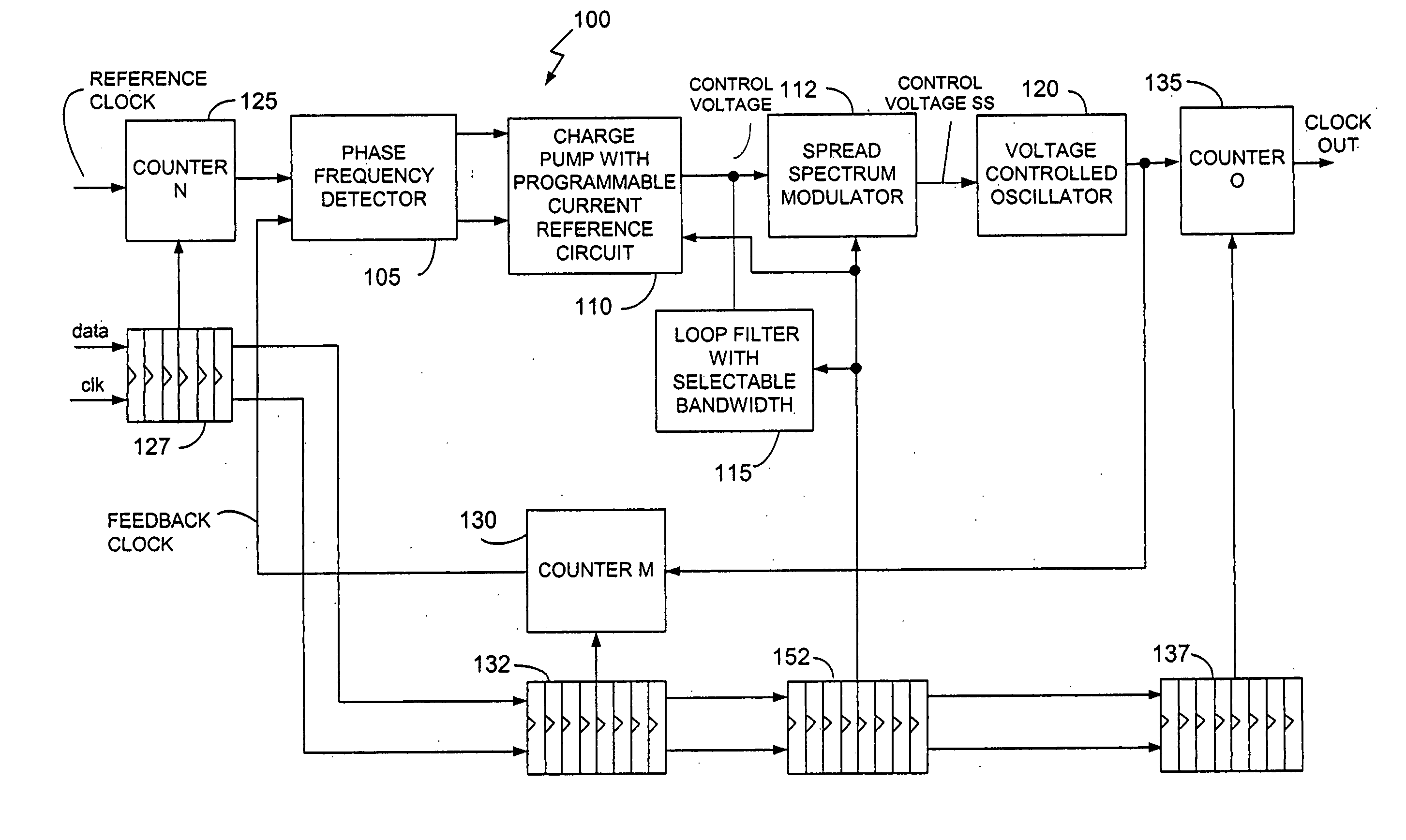
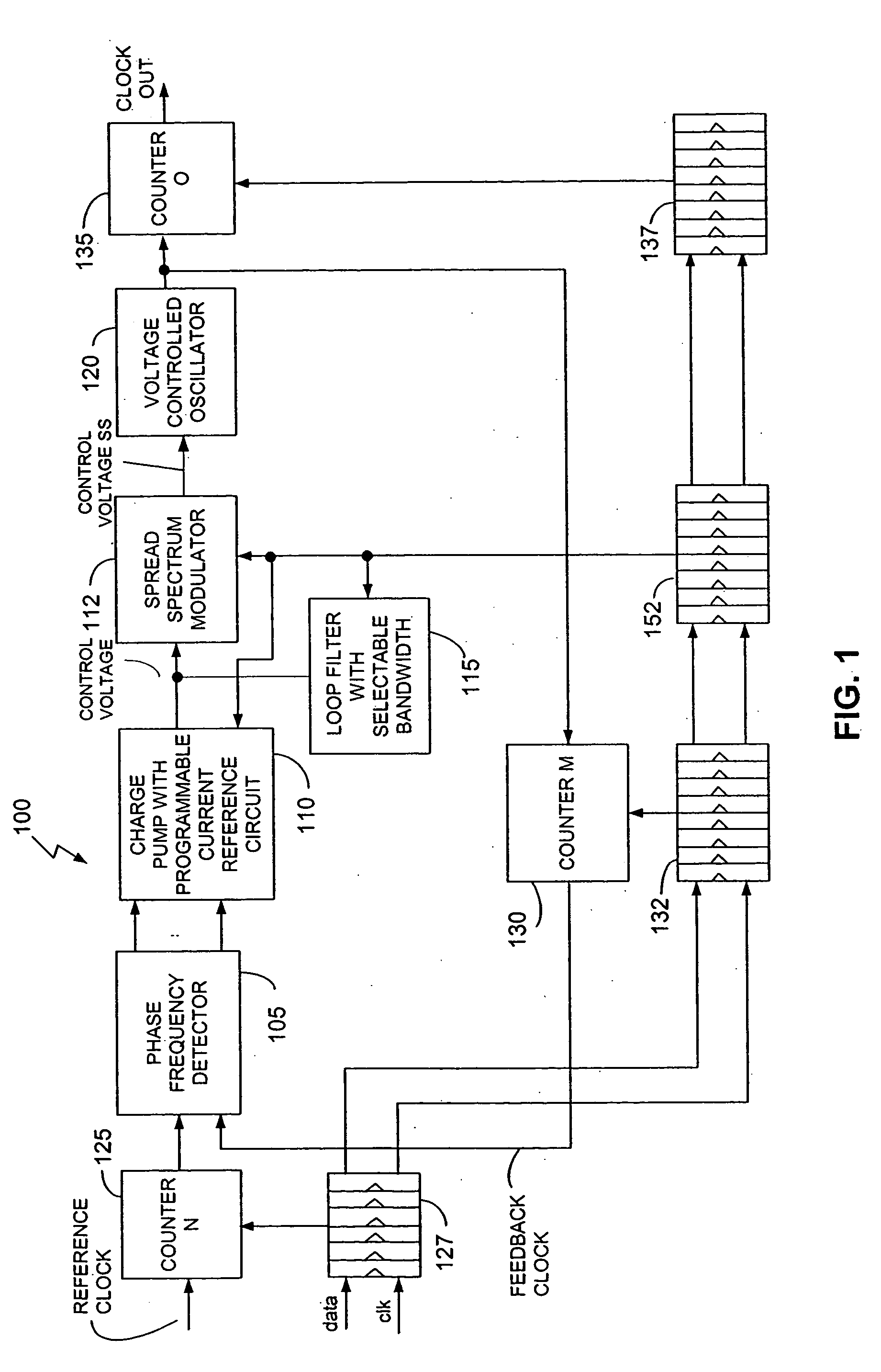
[0016] The present invention comprises a PLL circuit with an analog spread spectrum modulator. The following description is presented to enable any person skilled in the art to make and use the invention, and is provided in the context of a particular application and its requirements. Various modifications to the embodiments shown will be readily apparent to those skilled in the art, and the generic principles defined herein may be applied to other embodiments and applications without departing from the spirit and scope of the invention. Thus, the present invention is not intended to be limited to the embodiments shown, but is to be accorded the widest scope consistent with the principles and features disclosed herein.

[0017] The present invention is primarily described and claimed with reference to a PLL circuit. It is to be noted, however, that PLL and delay locked loop (DLL) circuits are herein used interchangeably. Therefore, references herein to a PLL circuit, either in the des...


PUM


Abstract

A PLL circuit is described. The PLL circuit includes: a signal generator; and a spread spectrum modulator coupled to the signal generator, where the spread spectrum modulator receives a control voltage as an input and provides a spread spectrum control voltage to the signal generator in response to the control voltage. In one embodiment, the spread spectrum modulator includes at least one selector, where the at least one selector selects a plurality of voltage levels that correspond to a spread mode and percentage of spread for the spread spectrum modulator.

Description

CROSS-REFERENCE TO RELATED APPLICATIONS [0001] This application claims the benefits of U.S. Provisional Application Ser. Nos. 60 / 289,268 and 60 / 289,245, filed May 6, 2001, and entitled “Programmable Loop Bandwidth In Phase Locked Loop (PLL) Circuit” and “Phase Lock Loop (PLL) And Delay Lock Loop (DLL) Counter And Delay Element Programming In User Mode”, respectively.[0002] This application is being filed concurrently with (1) the U.S. patent application of Gregory W. Starr and Wanli Chang for “Programmable Loop Bandwidth In Phase Locked Loop (PLL) Circuit”, (2) the U.S. patent application of Gregory W. Starr, Yen-Hsiang Chang, and Edward P. Aung for “Phase Locked Loop (PLL) And Delay Locked Loop (DLL) Counter And Delay Element Programming In User Mode”, and (3) the U.S. patent application of Wanli Chang and Gregory W. Starr for “Programmable Current Reference Circuit”, and incorporates the material therein by reference. BACKGROUND OF THE INVENTION [0003] 1. Field of the Invention [0...

Claims


Application Information

Patent Timeline
IPC IPC(8): H03L7/089H03L7/093H03L7/18H03M1/80H04B1/707H04L7/033
CPCH03L7/0896H03L7/0898H03L7/093H04B1/707H03L7/1803H03M1/808H03L7/18
Inventor STARR, GREGORY W.CHANG, WANLI
Owner ALTERA CORP
Why Eureka
Try Eureka