Illumination apparatus

a technology of illumination apparatus and back, which is applied in the direction of mechanical apparatus, lighting and heating apparatus, instruments, etc., can solve the problems of uneven brightness, inability to avoid uneven brightness, and point light sources that cannot be converted into uniform plane light sources, etc., and achieves low cost and satisfactory workability.

Inactive Publication Date: 2005-02-10
SEMICON ENERGY LAB CO LTD
View PDF21 Cites 41 Cited by
  • Summary
  • Abstract
  • Description
  • Claims
  • Application Information

AI Technical Summary

Benefits of technology

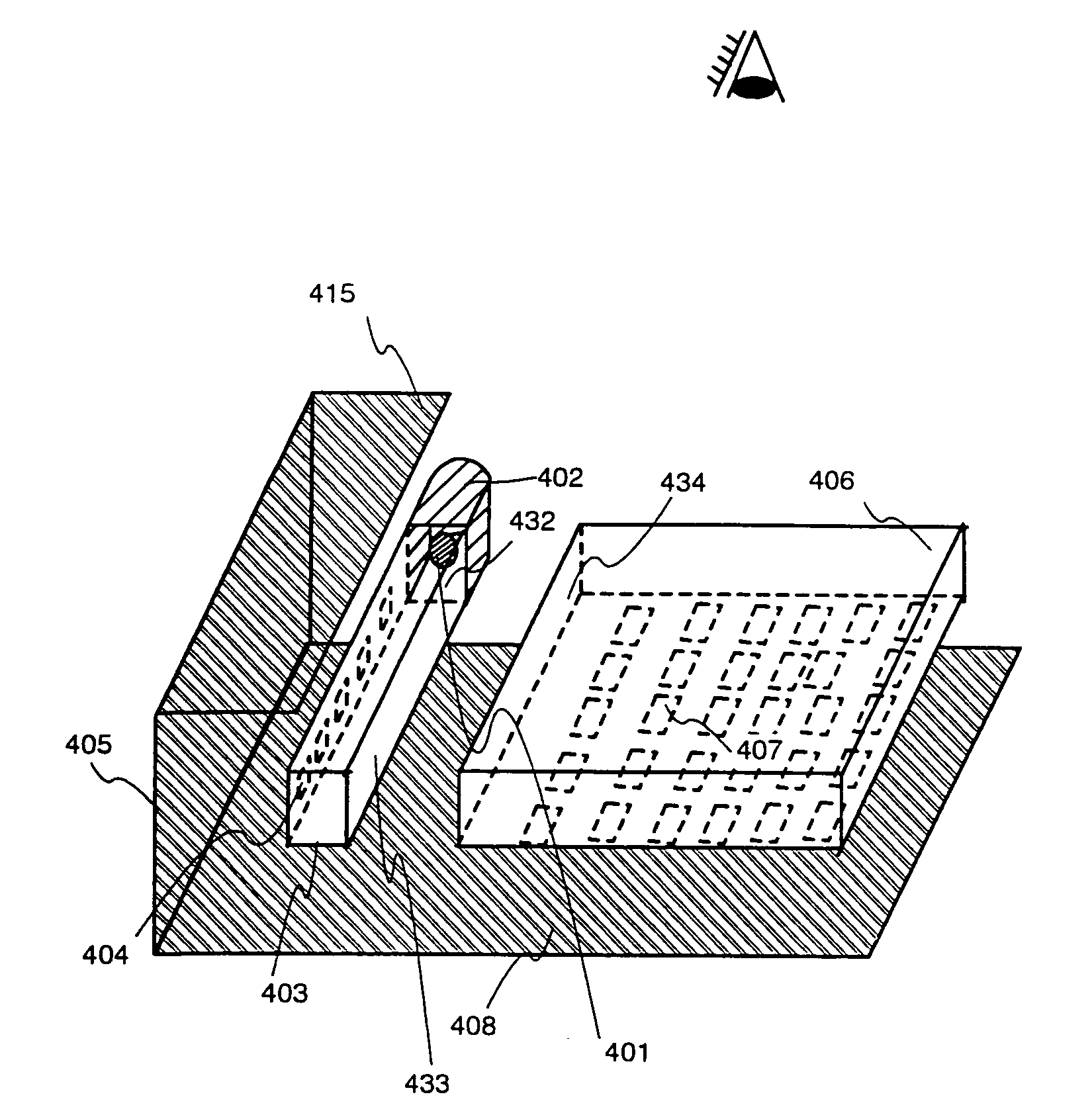
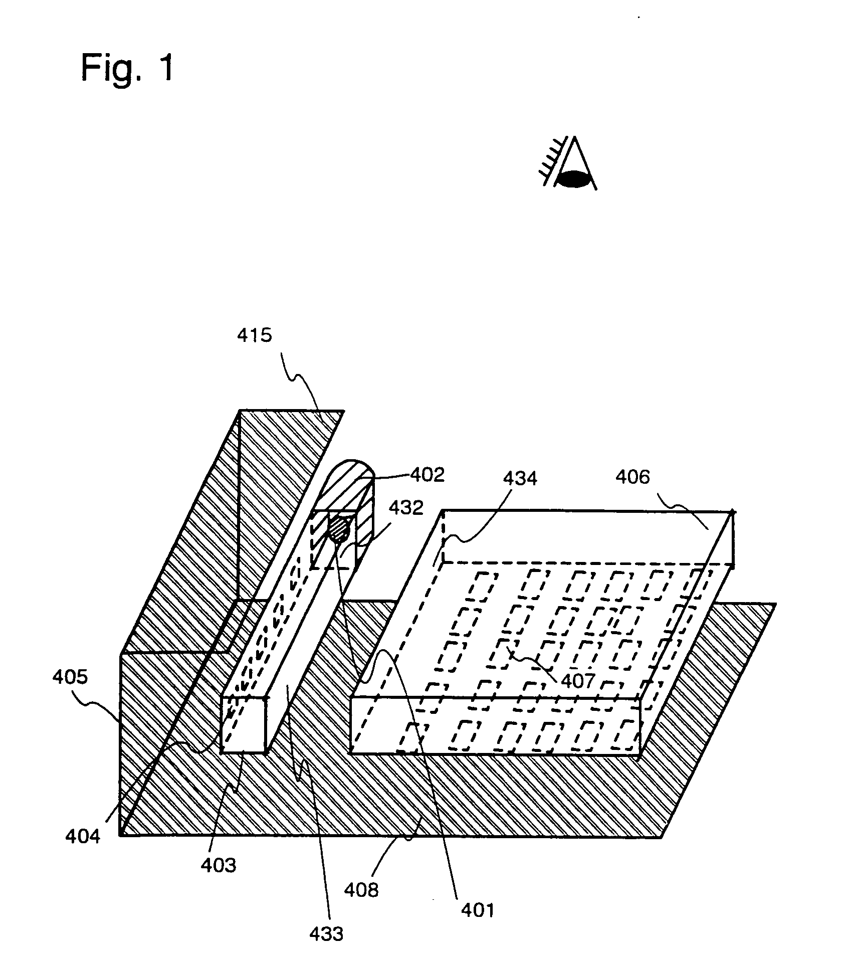
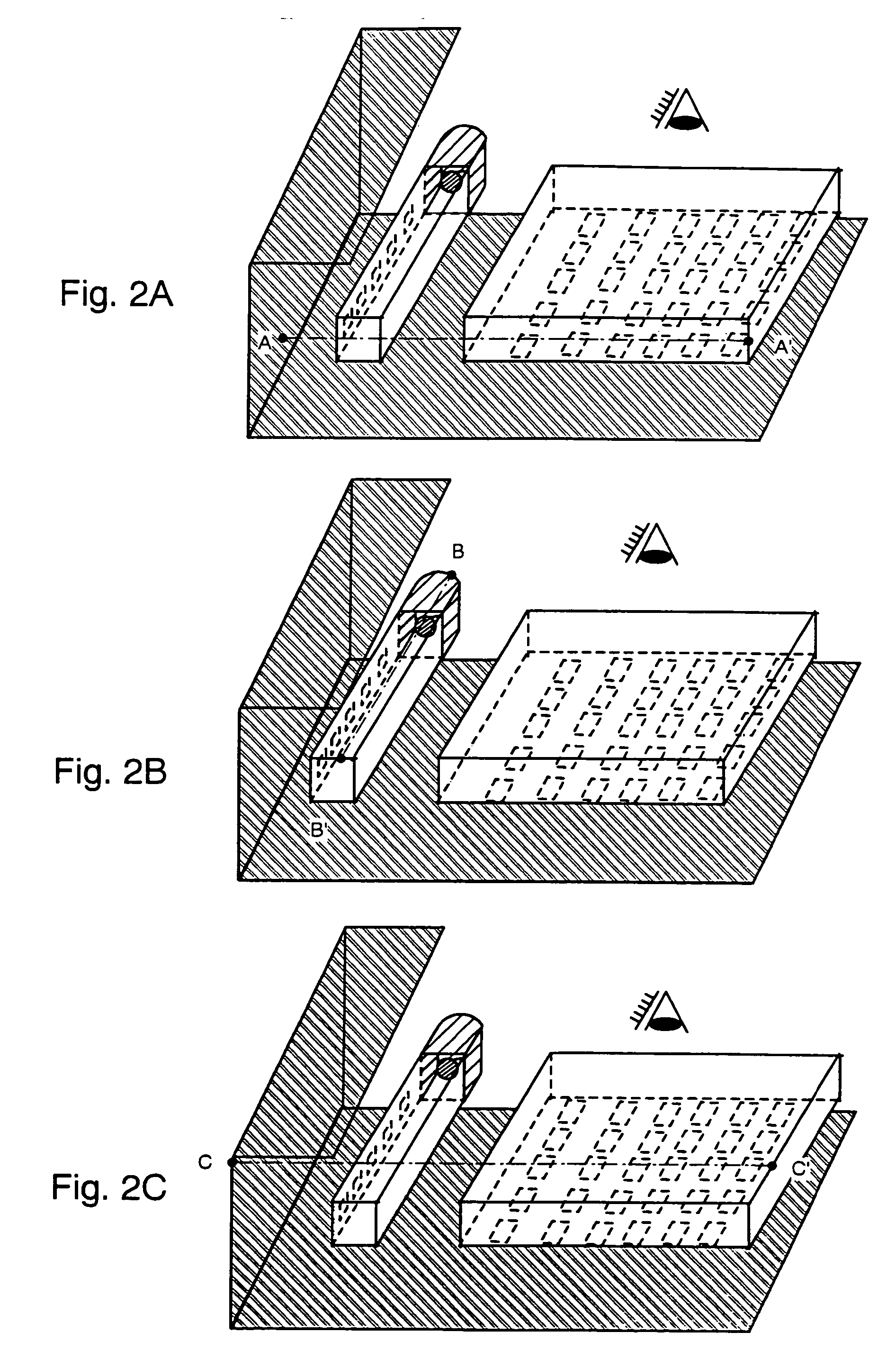
[0019] In accordance with the present invention, a point light source is converted into a line light source by means of a linear light guiding plate, and further into a plane light source by means of a plane-like light guiding plate. Thus, the plane light source having less unevenness in the brightness can be formed even when a point light source is employed.
[0038] Although the light emitting diode has been described as the point light source, application of the present invention is not limited to the light emitting diode. The present invention can be widely employed as means for converting a point light source into a plane light source. The plate-like light guiding plate in accordance with the present invention may have a shape such as a rectangular parallelepiped which has satisfactory workability. Thus, a back light can be produced at a low cost.

Problems solved by technology

However, when the cold cathode fluorescent tube is used as the light source, most of power consumption of the liquid crystal display device is derived from the back light or the front light.
In an attempt where a point light source such as a light emitting diode is converted into a plane light source so as to obtain a uniform lightness in a large area, unevenness in the brightness cannot be avoided.
However, even when a plurality of point light sources are disposed on the side surface of the plate-like light guiding plate, these point light sources can not be converted into a uniform plane light source.
With a large unevenness in the brightness, the visibility is significantly damaged.

Method used


Image

  • Illumination apparatus
  • Illumination apparatus
  • Illumination apparatus

Examples


embodiment 1

[0115] [Embodiment 1]

[0116] A manufacturing method of a transmission type liquid crystal electro-optical device to be combined with the present invention will be described with reference to FIGS. 12A to 12C, 13A to 13C, 14A, 14B, 15, and 16. Like portions are designated with like reference numerals in FIGS. 12A to 12C, 13A to 13C, 14A, 14B, 15, and 16. A chain line F-F′ in FIG. 14B corresponds to a cross-sectional view obtainable by cutting FIG. 16 along the chain line F-F′.

[0117] An active-matrix substrate includes gate wiring arranged in the row direction, source wiring arranged in the column direction, a pixel portion having pixel TFTs respectively provided in the vicinity of crossing points of the gate wiring and the source wiring, and a driver circuit including an n-channel TFT and a p-channel TFT. The term “gate wiring” refers herein to a structure in which the gate wiring arranged in the row direction is electrically connected to a gate electrode via a contact hole.

[0118] I...

embodiment 2

[0170] [Embodiment 2]

[0171] The lighting apparatus formed by implementing the present invention can be used in a variety of electro-optical devices. Namely, the present invention can be implemented for all electronic equipment, which incorporates this type of electro-optical device in a display portion. The following can be given as such electronic equipment: a personal computer, a digital camera, a video camera, a portable information terminal (such as a mobile computer, a portable telephone, or an electronic book) and a navigation system. Some examples of these are shown in this embodiment.

[0172]FIG. 17A shows a portable telephone, and contains components such as a main body 9001, an audio output portion 9002, an audio input portion 9003, a display portion 9004, operation switches 9005, and an antenna 9006. The present invention can be applied to the display portion 9004 having an active matrix substrate.

[0173]FIG. 17B shows a video camera and contains components such as a main ...


PUM


Abstract

A point light source is converted into a plane light source having a satisfactory uniformity. The point light source is converted into a line light source by means of a linear light guiding plate, and further into the plane light source by means of a plane-like light guiding plate. Light from the point light source is reflected at a lamp reflector to be incident on at least two side surfaces of the plane-like light guiding plate.

Description

BACKGROUND OF THE INVENTION [0001] 1. Field of the Invention [0002] The present invention relates to an illumination apparatus for illuminating an image display plane of a liquid crystal display device, and more specifically, relates to a scheme intended to realize a uniform in-plane brightness of the illumination apparatus in a method for converting a point light source into a plane light source. By means of the present invention, an illumination apparatus capable of emitting light as a plane light source with no unevenness in brightness can be realized even when a point light source is employed. In addition, by means of the present invention, an illumination apparatus capable of emitting light as a plane light source with less unevenness in brightness can be realized even when the small number of point light sources is employed. [0003] 2. Description of the Related Art [0004] A liquid crystal electro-optical device is widely used in view of advantages of low power consumption, lig...

Claims


Application Information

Patent Timeline
Patent Type & Authority Applications(United States)
IPC IPC(8): F21V8/00
CPCG02B6/0028G02B6/0031G02B6/0038G02B6/0043G02F1/1336G02B6/0055G02F1/133615H01L29/786G02B6/0046
Inventor KIMURA, HAJIMESATAKE, RUMO
Owner SEMICON ENERGY LAB CO LTD
Why Eureka
Try Eureka