Optical disk device

a technology of optical disk and optical disk, which is applied in the direction of optical beam sources, instruments, disposition/mounting of heads, etc., can solve the problem of reducing the intensity of the light beam once the device is installed

Inactive Publication Date: 2005-02-10
KONO KAZUHIKO
View PDF15 Cites 13 Cited by
  • Summary
  • Abstract
  • Description
  • Claims
  • Application Information

AI Technical Summary

Benefits of technology

[0023] An optical disk device is capable of avoiding wrong recording or wrong erasing of a signal in a region of the disk where the signal is not intended to be recorded in the case that a focus control is disturbed during the recording operation due to disturbance, vibration or physical defect of the disk, or in the case of recording over plural layers.
[0025] Further, when moving the data plane followed by the light beam during a recording operation to a data plane of another layer, the device once reduces the intensity of the light beam. After moving the light beam to another layer, the device raises the intensity of the light beam again.

Problems solved by technology

Further, when moving the data plane followed by the light beam during a recording operation to a data plane of another layer, the device once reduces the intensity of the light beam.

Method used


Image

  • Optical disk device
  • Optical disk device
  • Optical disk device

Examples


embodiment 1

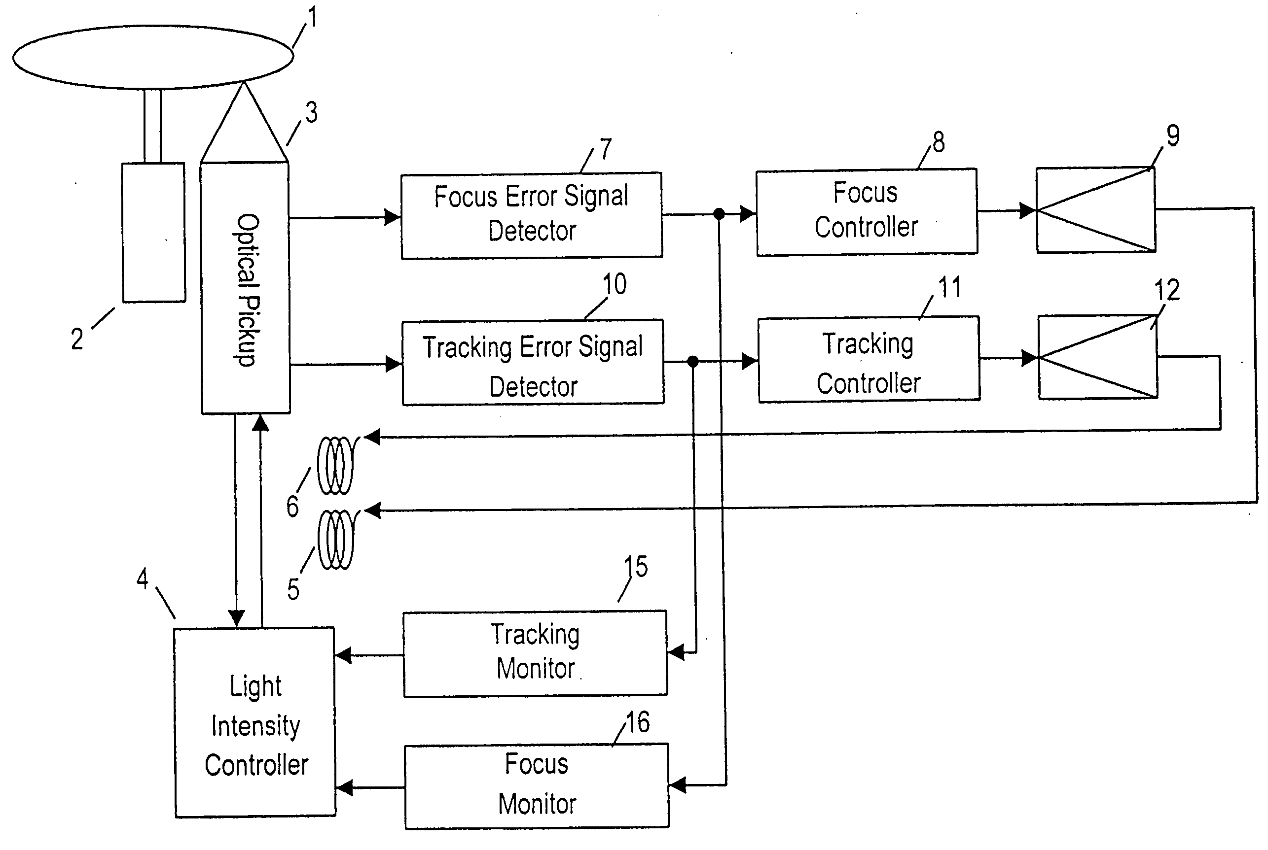
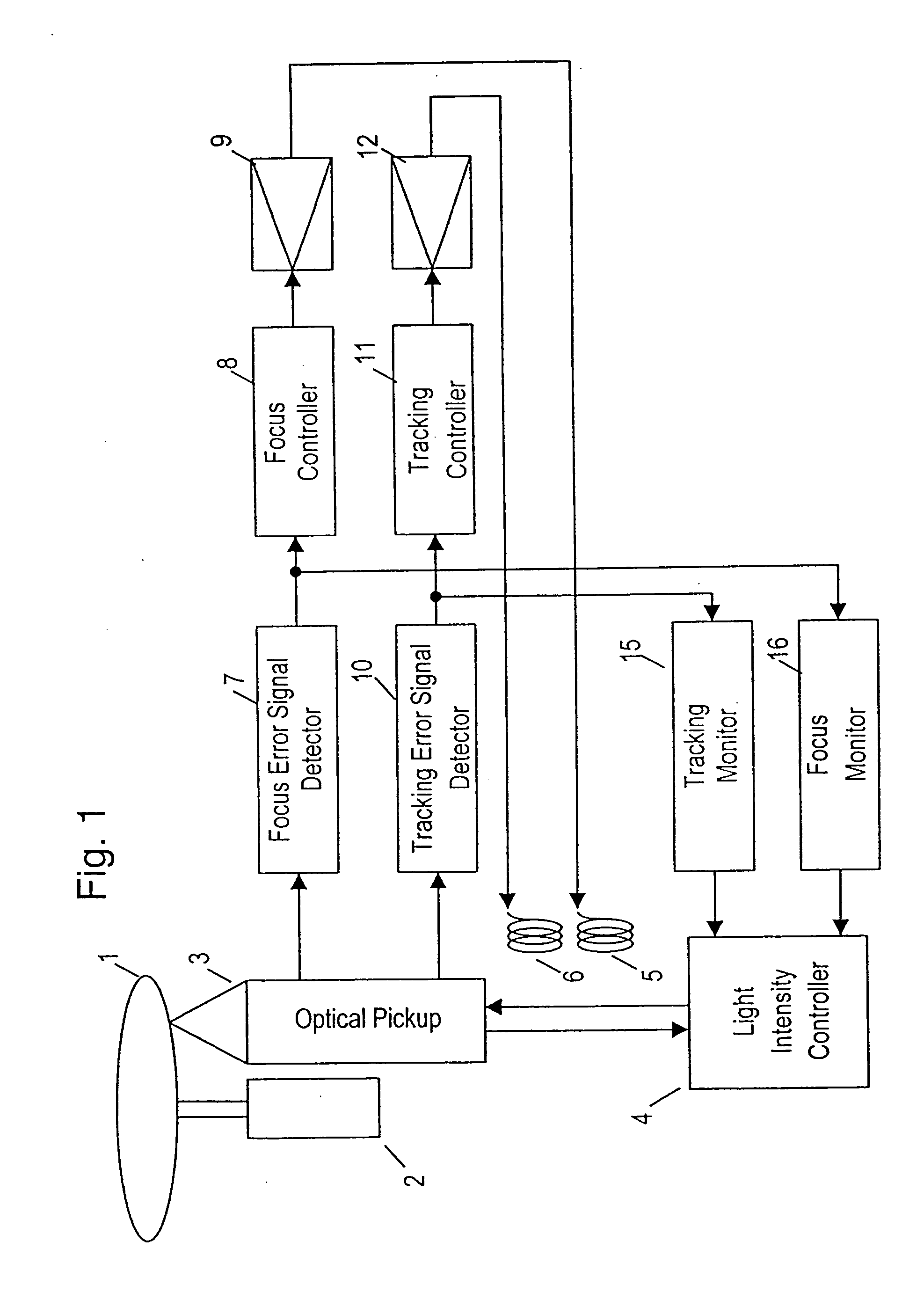
[0037]FIG. 1 is a block diagram showing a schematic configuration of an optical disk device according to exemplary embodiment 1 of the present invention. In FIG. 1, elements 1 to 12 and 15 are the same as in the conventional optical disk device shown in FIG. 7, and their explanation will be omitted. A focus monitor 16 monitors an increase of an amplitude of a focus error signal issued by a focus error detector 7 and issues a light intensity reducing command signal to a light intensity controller 4 when the amplitude exceeds a specified reference.

[0038] An operation of the device of embodiment 1 will be explained in FIG. 5.

[0039]FIG. 5 shows a focus error signal and light intensity reducing command signal under the condition that the focus control during recording is out of order due to disturbance, vibration or physical defect of the disk. A low level of the light intensity reducing command signal reduces the light intensity. The focus monitor 16 compares a specified reference th1...

embodiment 2

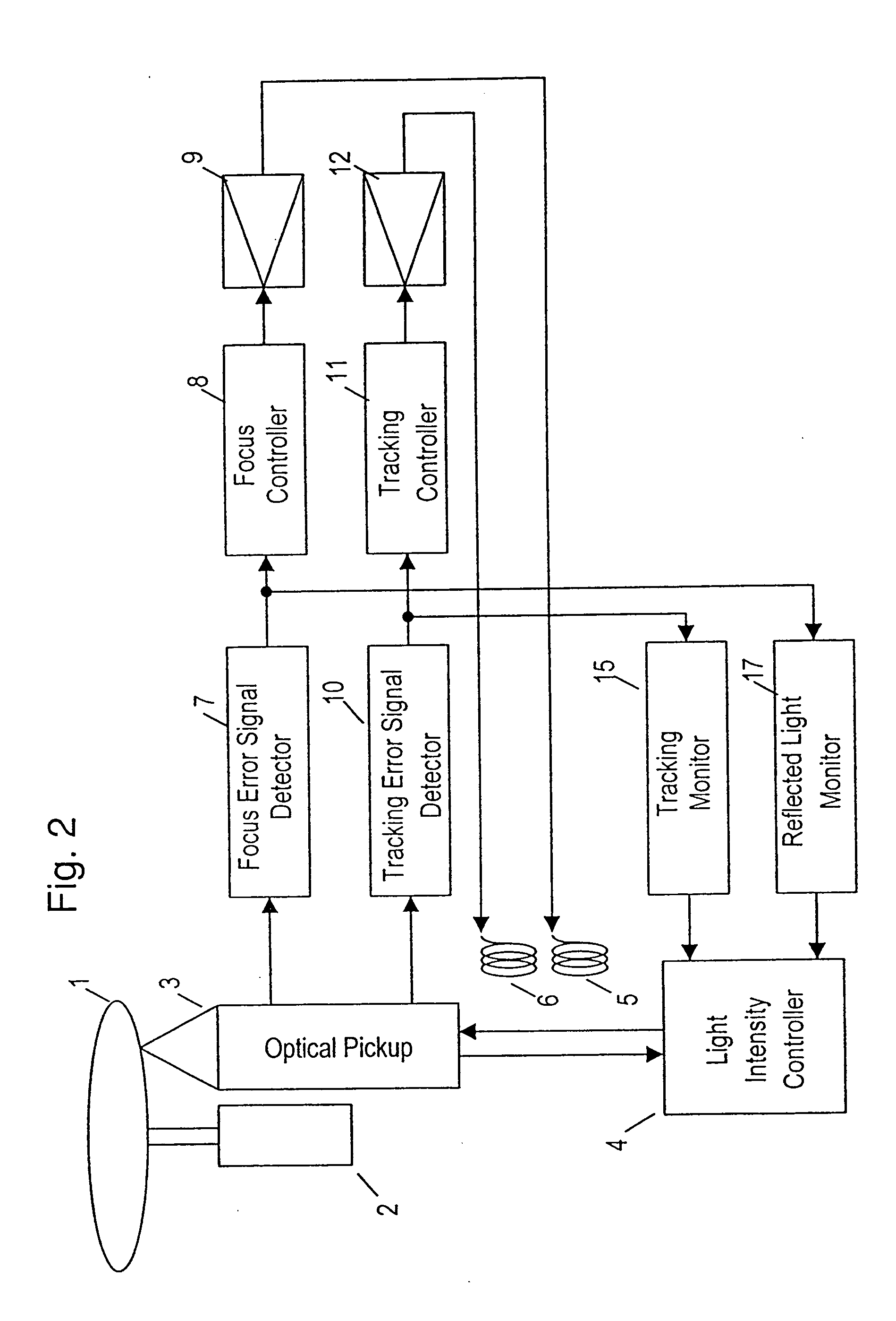
[0044]FIG. 2 is a block diagram showing a schematic configuration of an optical disk device according to exemplary embodiment 2 of the present invention.

[0045] In FIG. 2, elements 1 to 12 and 15 are the same as in the conventional optical disk device shown in FIG. 7, and their explanation is omitted. A reflected light quantity monitor 17 detects the quantity of a light reflected from the optical disk 1 and monitors a drop of the amplitude of the light. When the amplitude becomes smaller than a specified reference, the monitor 17 issues a light intensity reducing command signal to a light intensity controller 4.

[0046] An operation of the device of embodiment 2 is explained in FIG. 6.

[0047]FIG. 6 shows waveforms of a reflected light quantity signal and a light intensity reducing command signal at the moment when the focus control is out of order due to disturbance, vibration or physical defect of the disk while the focus of the light beam follows the first data plane S1 and recordi...

embodiment 3

[0050]FIG. 3 is a block diagram showing a schematic configuration of an optical disk device according to exemplary embodiment 3 of the present invention.

[0051] In FIG. 3, elements 1 to 12 and 15 are the same as in the conventional optical disk device shown in FIG. 7, and their explanation is omitted. An address detector 18 detects address data on which a signal is recorded on the disk on the basis of the quantity of a light reflected from the optical disk 1. A layer move detector 19 detects, on the basis of the address data, that the data plane followed by the light beam moves to another layer and issues a light intensity reducing command signal to a light intensity controller 4.

[0052] An operation of the device of embodiment 3 having such configuration will be explained.

[0053] While a signal is recorded as the focus of the light beam follows the first data plane S1 by focus control, if the focus control is disturbed due to disturbance, vibration or physical defect of the disk, t...


PUM

PropertyMeasurementUnit
densityaaaaaaaaaa
frequencyaaaaaaaaaa
light intensityaaaaaaaaaa

Abstract

An optical disk device is capable of preventing a signal from being incorrectly recorded or erased on another data plane different from a data plane in a recording operation on a disk having plural layers of data plane. A focus monitor monitors an increase of a focus error signal. A reflected light quantity monitor may monitor a drop of reflected light quantity. A move from a layer of a data plane during recording may be detected. Depending on these results, a light intensity controller reduces an intensity of a light beam to a reproducing level. The light intensity controller once reduces the intensity to a reproducing level when recording signals in plural layers of data plane. After moving to the layer followed by the focus of the light beam, the intensity of the light beam is raised again to the recording level.

Description

[0001] This application is a continuation application of U.S. application Ser. No. 09 / 890,576, filed Oct. 18, 2001, which is a National Stage Application of International Application No. PCT / JP00 / 08805, filed Dec. 13, 2000.FIELD OF THE INVENTION [0002] The present invention relates to an optical disk device for recording data in an optical disk having plural layers of data planes. BACKGROUND OF THE INVENTION [0003] Recently, technology for high density recording for an optical disk has intensively developed. For high density recording, the disk having multiple data layers is extremely effective. For an existing digital versatile disk (DVD), a two-layer play-only disk is already standardized. As of recently, recordable two-layer disks are being developed, which are expected to substantially enhance a recording capacity of an optical disk. [0004] An optical disk device using this technology will be explained below referring to the drawings. [0005]FIG. 7 is a block diagram showing a sc...

Claims


Application Information

Patent Timeline
Patent Type & Authority Applications(United States)
IPC IPC(8): G11B7/00G11B7/126G11B7/0037G11B7/004G11B7/0045G11B7/005G11B7/0055G11B7/085G11B7/09G11B7/125
CPCG11B7/0037G11B7/004G11B7/0045G11B7/08511G11B2007/0013G11B7/0908G11B7/0946G11B7/0948G11B7/126G11B7/0901G11B7/24038G11B7/08547G11B2220/2537
Inventor KONO, KAZUHIKO
Owner KONO KAZUHIKO
Why Eureka
Try Eureka