Mode multiplexing optical coupling device

Inactive Publication Date: 2005-02-10
COHERENT INC
View PDF24 Cites 20 Cited by
  • Summary
  • Abstract
  • Description
  • Claims
  • Application Information

AI Technical Summary

Benefits of technology

It is an object of the present invention to obviate or mitigate at least one disadvantage of previous optical coupling devices, such as combiners and splitters. It is a particular object

Problems solved by technology

First, the etendue on the input side should be less than or equal to the etendue on the output side, otherwise the coupling efficiency will be limited by Eout/Ein.
However, it is not possible t

Method used


Image

  • Mode multiplexing optical coupling device
  • Mode multiplexing optical coupling device
  • Mode multiplexing optical coupling device

Examples


Example

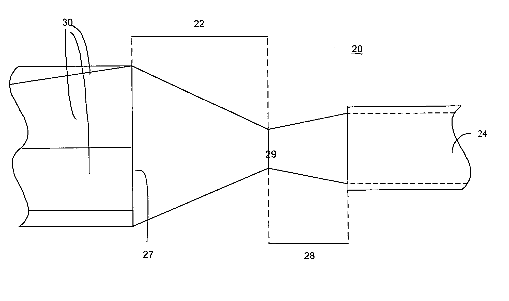
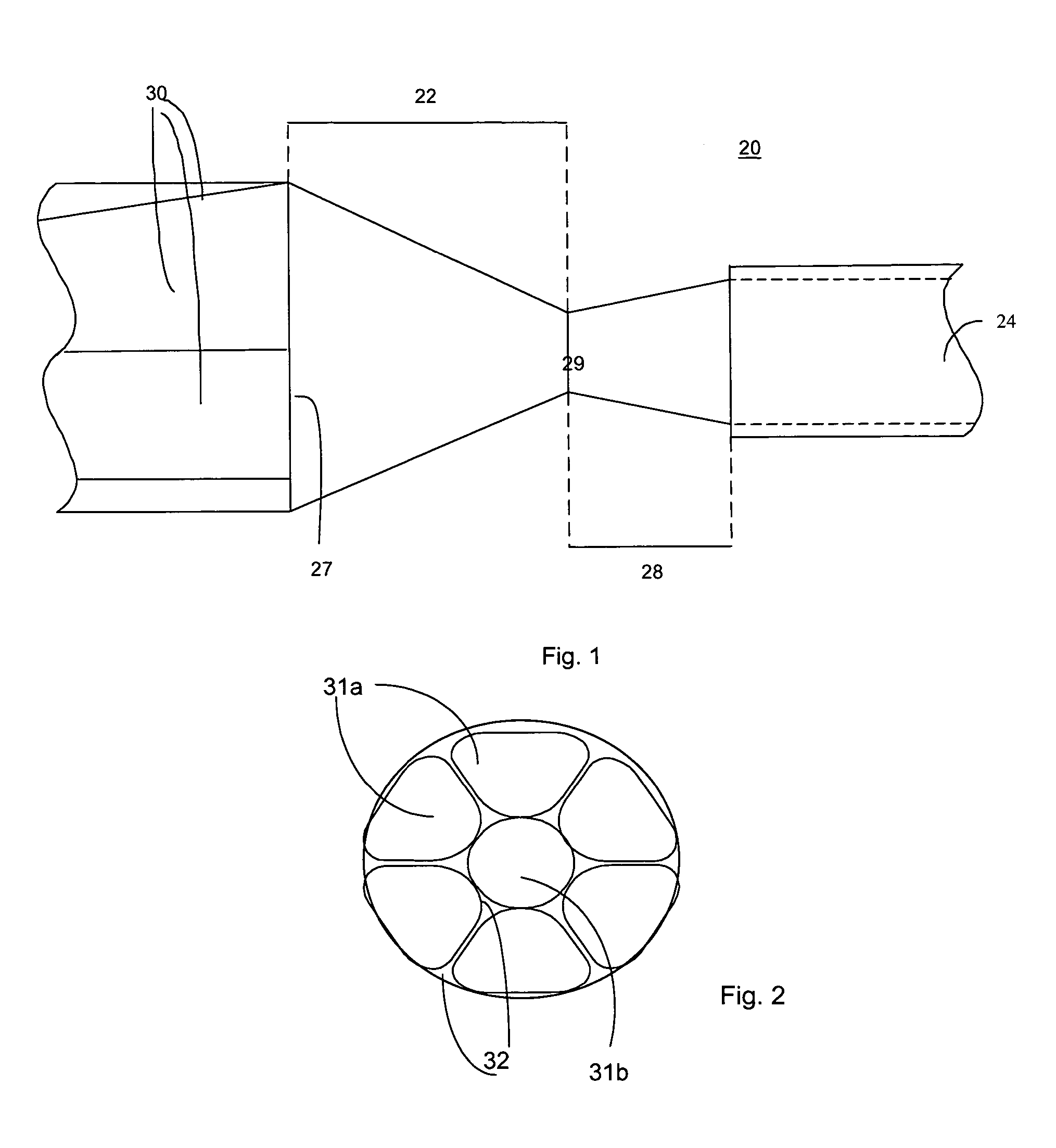
Generally, the present invention provides a mode multiplexing optical coupling device, and a method of making such a device. The optical device, and related fabrication process, have one or more input fibers that are fused and tapered and can be coupled to one or more output fibers, such that the optimum cross-sectional shape of the fused region depends on the specific details of the output fiber or fibers. For ease of description, the following discussion is limited to the case of a mode multiplexing combiner having a single output fiber of circular cross-section. However, this is not intended to limit the generality of the present invention, and it is clearly within the contemplation of the inventors that the present invention can be used with multiple output fibers, and / or with output fibers having non-circular cross-sections.

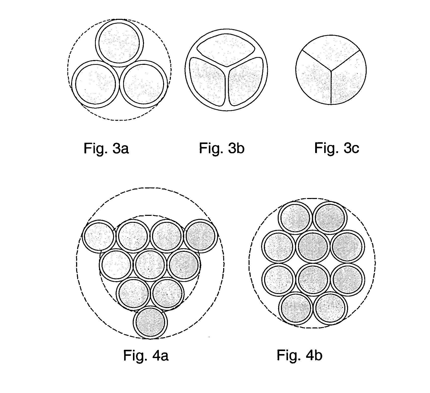
The object of a mode multiplexing combiner is to maximize the transfer of power by maximizing the number of multimode fibers of specified NA and core dia...


PUM


Abstract

An efficient tapered optical fiber bundle along with the method of manufacturing is presented. The tapered fiber bundle is fully fused to an induced shape with no interstitial space between fibers. To minimize fiber deformation and hence the tapered bundle's loss, the individual fibers are minimally deformed by positioning them in a fixture with predetermined geometry prior to fusion. The bundle could be optionally reshaped after fusion. The tapered bundle could then be used in its original form as a star coupler, or it could be cleaved and coupled to a multimode fiber, a multi-clad fiber, a cladding-pumped fiber, or an optical system to form an optical device. The resulting optical device has improved efficiency and lower loss compared with prior art devices.

Description

TECHNICAL FIELD OF THE INVENTION The present invention relates generally to optical devices. More particularly, the present invention relates to mode multiplexing optical coupling devices, such as mode multiplexing combiners for use with fiber lasers, fiber pumped solid-state lasers, and optical amplifiers, as well as to optical couplers and splitters based on mode managed optical coupling. BACKGROUND Fused coupler technology, wherein optical fibers are bundled together, heated, and pulled lengthwise, is commonly used to produce couplers, combiners and splitters for optical communication systems, medical devices and other industrial applications. Generally, a combiner is a passive fiber optic coupler in which power from several input fibers is combined into one output fiber. Conversely, a splitter divides light from a single input fiber into two or more output fibers. The coupler represents the general case where inputs from one or more fibers are mixed and distributed among one o...

Claims


Application Information

Patent Timeline
IPC IPC(8): G01T1/178G02B6/255G02B6/28
CPCG02B6/14G02B6/2552G02B6/2856G02B6/2835G02B6/2804
Inventor VAKILI, MASOUDALAVI-HARATI, ASHKANRIVETT, PAULYUAN, JINING
Owner COHERENT INC
Why Eureka
Try Eureka