Non-reciprocal device
- Summary
- Abstract
- Description
- Claims
- Application Information
AI Technical Summary
Benefits of technology
Problems solved by technology
Method used
Image
Examples
Embodiment Construction
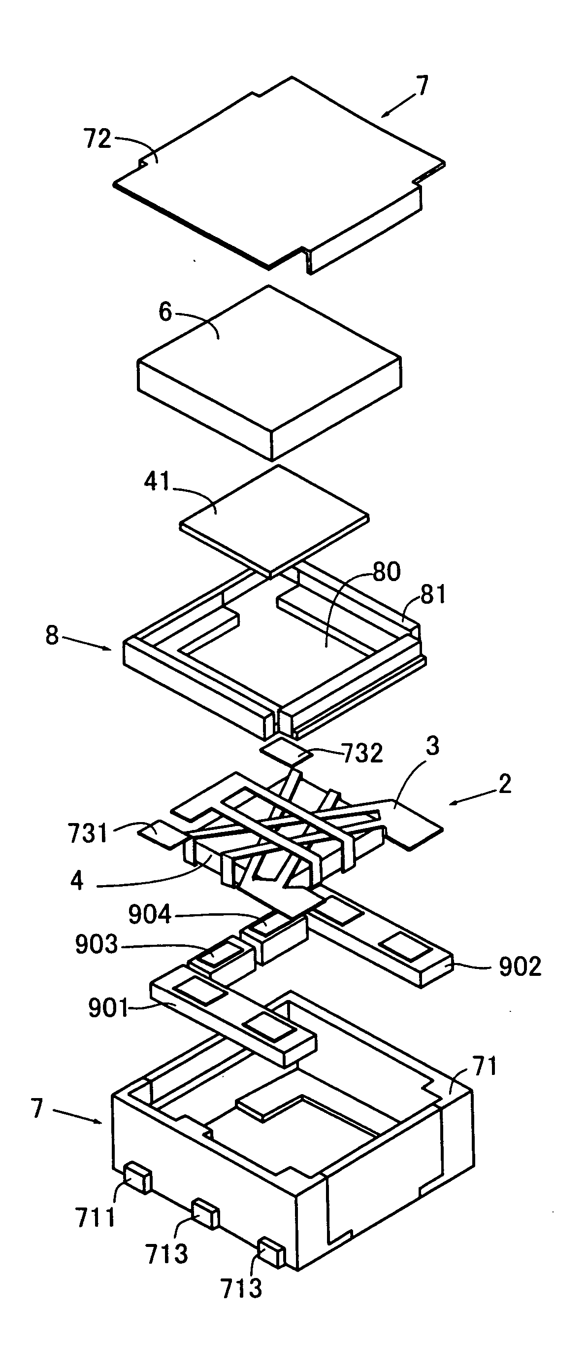
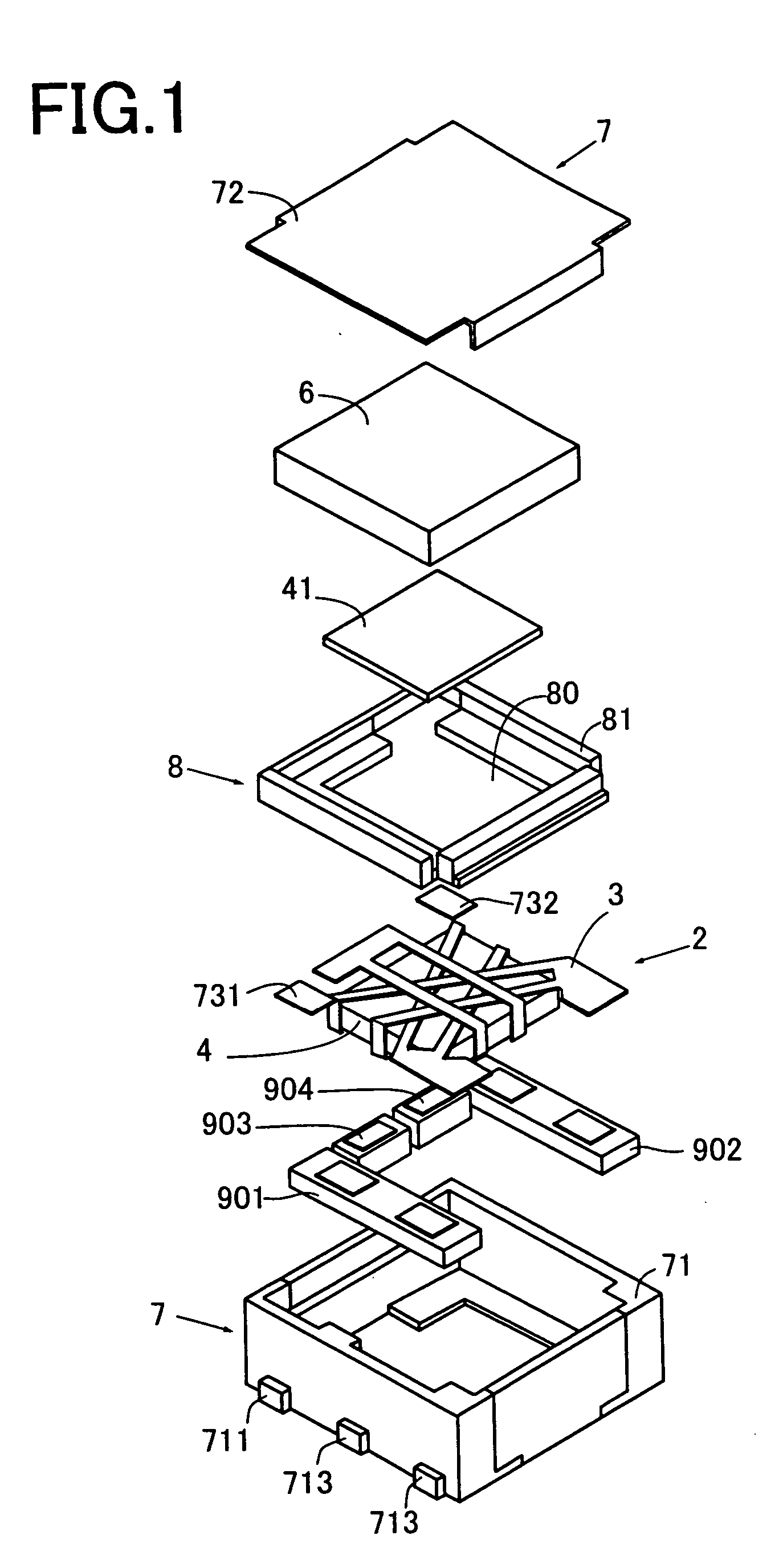
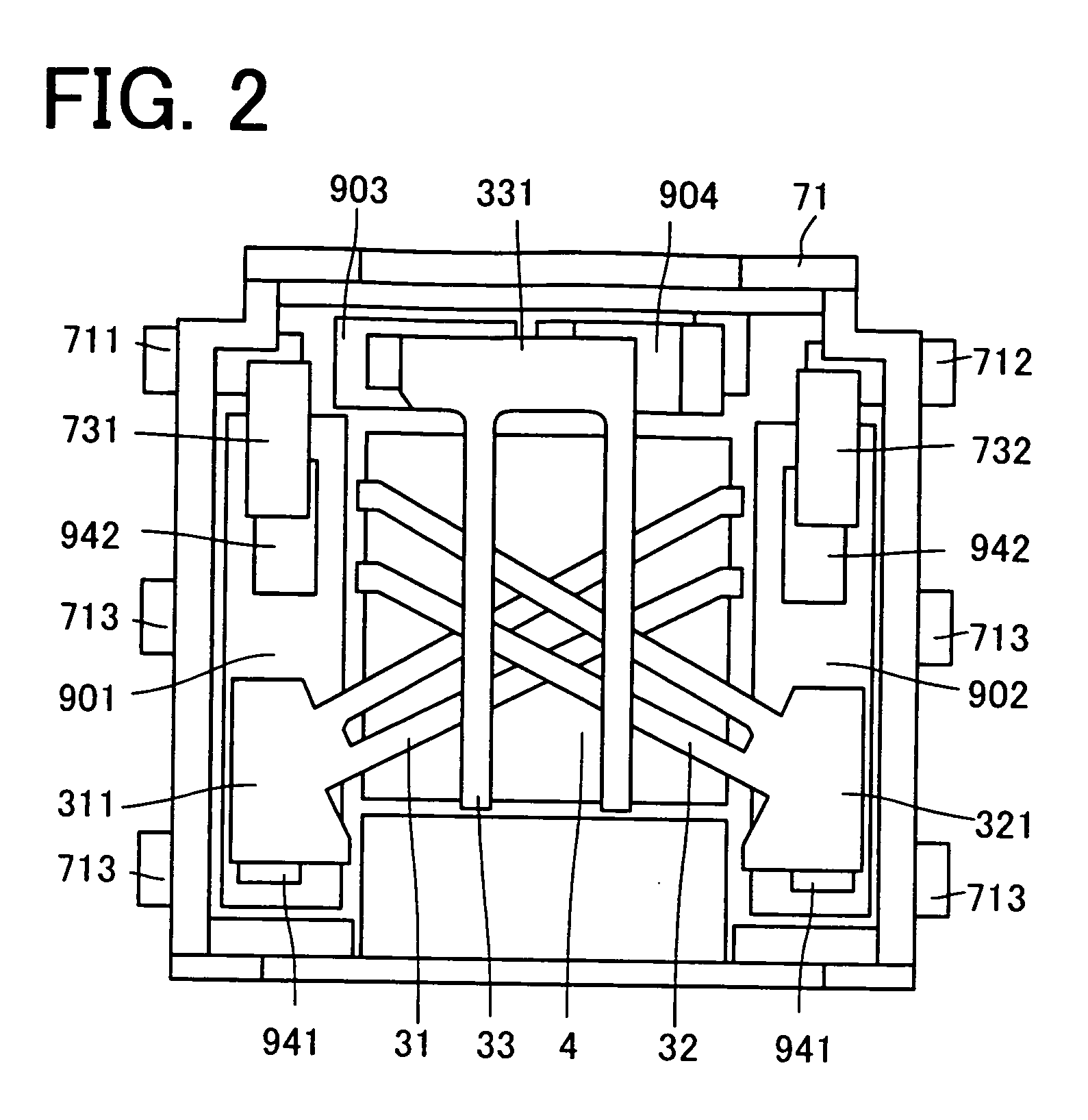
[0036]FIG. 1 is an exploded perspective view of a non-reciprocal device embodying the invention, FIG. 2 is a flat view of a gyromagnetic component of the non-reciprocal device shown in FIG. 1 for illustrating its assemblage, and FIG. 3 is the circuit diagram of the non-reciprocal device shown in FIGS. 1 and 2.
[0037] The non-reciprocal device 1 shown in the figures comprises a gyromagnetic component 2, a permanent magnet 6, a case 7, a pressing member 8, and electric components 901, 902, 903, 904.
[0038] The case 7 comprises an enclosure member 71 and a lid member 72. The enclosure member 71 comprises electrically conductive magnetic metal partitions and insulating resin partitions, has a shape like a box whose top is open, and has its bottom grounded (ground G potential). Each of the insulating partitions has terminals 711-713 for connecting internal circuit elements with external circuit elements. The enclosure member 71 houses the gyromagnetic component 2, permanent magnet 6, ele...
PUM
 Abstract
Description
Claims
Application Information
 - R&D
- Intellectual Property
- Life Sciences
- Materials
- Tech Scout
- Unparalleled Data Quality
- Higher Quality Content
- 60% Fewer Hallucinations
Browse by: Latest US Patents, China's latest patents, Technical Efficacy Thesaurus, Application Domain, Technology Topic, Popular Technical Reports.
© 2025 PatSnap. All rights reserved.Legal|Privacy policy|Modern Slavery Act Transparency Statement|Sitemap|About US| Contact US: help@patsnap.com


