Adaptive optical transponder

Active Publication Date: 2005-02-10
OPLINK COMM
View PDF4 Cites 22 Cited by
  • Summary
  • Abstract
  • Description
  • Claims
  • Application Information

AI Technical Summary

Benefits of technology

In general, in another aspect a method of Blind Channel Initialization is provided. The method includes: i) collecting a set of error measurements corresponding to different permutations of elements belonging to at least one tap-weight vector; and ii) selecting the permutation of the elements of the at least one tap-weight vector that corresponds to a minimum error measurement collected in step i). The following specification can be implemented to provide some or all of the following advantages. A joint electro-optical distortion compensation system is provided to simplify an optical communication system, thus reducing costs and making the optical communication system more versatile. The joint electro-op

Problems solved by technology

Dispersion is a significant source of signal distortion.
Controlling dispersion is becoming

Method used


Image

  • Adaptive optical transponder
  • Adaptive optical transponder
  • Adaptive optical transponder

Examples


Embodiment Construction

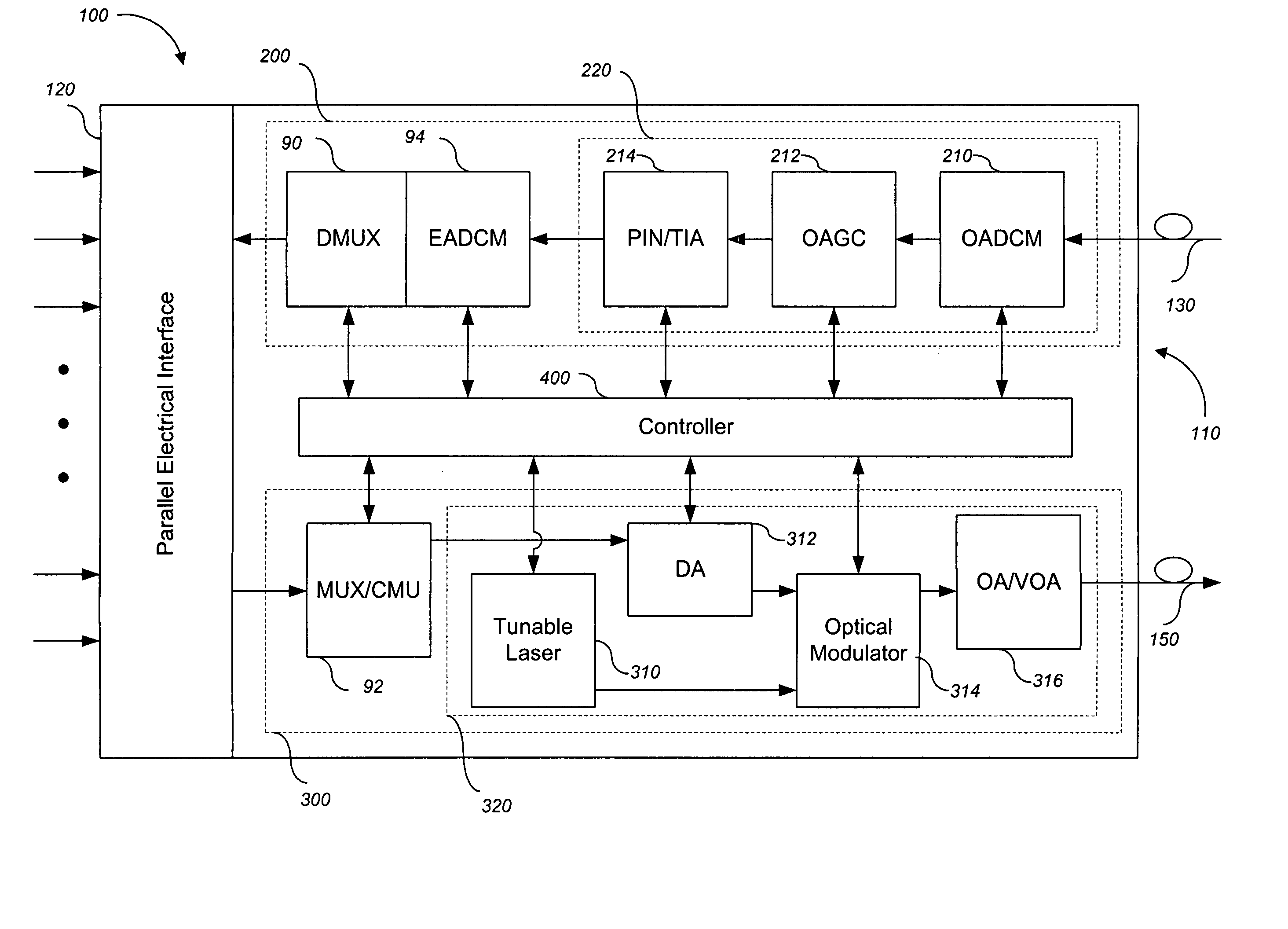
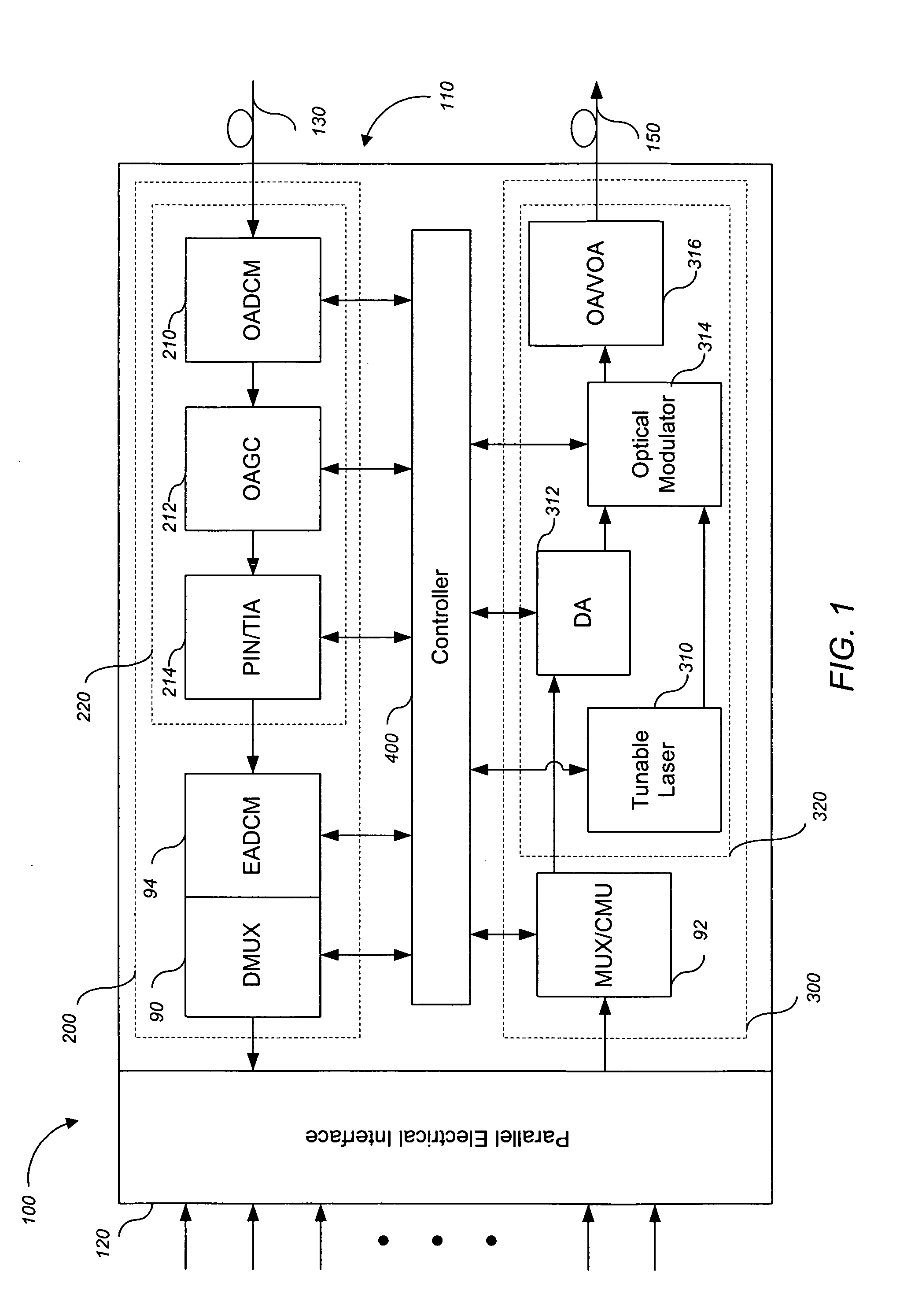
Shown in FIG. 1 is a schematic view of an adaptive optical transponder 100 according to one implementation. The adaptive optical transponder 100 includes a reception signal chain 200, a transmission signal chain 300, a parallel electrical interface 120, and a controller 400. An optical input terminal 130 and an optical output terminal 150 are used to couple corresponding optical signals into and out of the reception signal chain 200 and transmission signal chain 300 respectively. In one implementation, illustrated by FIG. 1, both the reception signal chain 200 and transmission signal chain 300 share access to the parallel electrical interface 120.

The controller 400 is coupled to both the reception transmission signal chain 200 and the transmission signal chains 300 at various points in order to receive information and deliver control signals to components within each signal chain. In one implementation, the controller 400 can be a microprocessor alone or a microprocessor in combi...


PUM


Abstract

Systems and methods for optical communications. In one implementation, a communications device is provided. The communications device includes an Optical domain Adaptive Dispersion Compensation Module (OADCM); an Electrical domain Adaptive Distortion Compensation Module (EADCM); and a controller coupled to, and operable to selectively control, both the OADCM and the EADCM.

Description

BACKGROUND The following specification relates to optical communications. Opto-electrical technologies have been developed to support the transmission and reception of optical signals through optical fiber channels, including controlling signal distortion induced by optical fibers. Dispersion is a significant source of signal distortion. Controlling dispersion is becoming increasingly difficult as optical communication systems progress towards higher data rates. Conventionally, dispersion compensation includes the use of dispersion compensators located at various points along an optical signal propagation path. SUMMARY Systems and methods for optical communications. In general, in one aspect, a communications device is provided. The communications device includes an Optical domain Adaptive Dispersion Compensation Module (OADCM), an Electrical domain Adaptive Distortion Compensation Module (EADCM), and a controller coupled to, and operable to selectively control, both the OADCM an...

Claims


Application Information

Patent Timeline
IPC IPC(8): G02BH04B10/06H04B10/08H04B10/12H04B10/18H04J14/08
CPCH04B10/25133
Inventor SHI, FENGZHANG, GENZAOFU, XIAOLILI, JINGHUIWANG, TONGQINGRALSTON, JOHNMATHEW, MONI G.
Owner OPLINK COMM
Why Eureka
Try Eureka