Connector

Inactive Publication Date: 2005-02-10
JST MFG CO LTD
View PDF5 Cites 72 Cited by
  • Summary
  • Abstract
  • Description
  • Claims
  • Application Information

AI Technical Summary

Benefits of technology

[0016] In the conventional connector, when a digital signal of several GHz is transmitted, since, in particular, a component with a high frequency attenuates largely, a digital waveform is dulled. In this case, if an amplifier is provided at an output terminal and only an attenuated high-frequency component is amplified by this amplifier, a waveform close to the digital waveform transmitted at an input terminal can be restored. However, since an amplifying IC excellent in high-frequency responsiveness is required in order to amplify such a high-frequency component, cost for a transmission system is increased.
[0017] Therefore, according to the invention of (1), the high pass filters are provided in the differential signal patterns of the transmission path board. That is, a high-frequency component of a digital signal is not amplified and a low-frequency component thereof is att

Problems solved by technology

However, in a portion where signals repeat reversal, it is likely that a signal is reversed due to a transient phenomenon before the signal reaches a pre

Method used


Image

  • Connector
  • Connector
  • Connector

Examples


Embodiment Construction

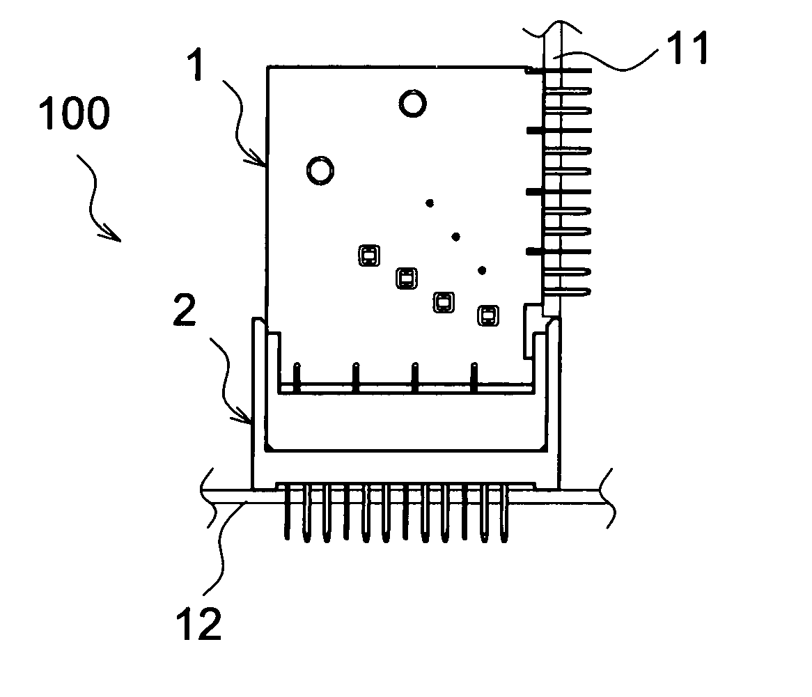
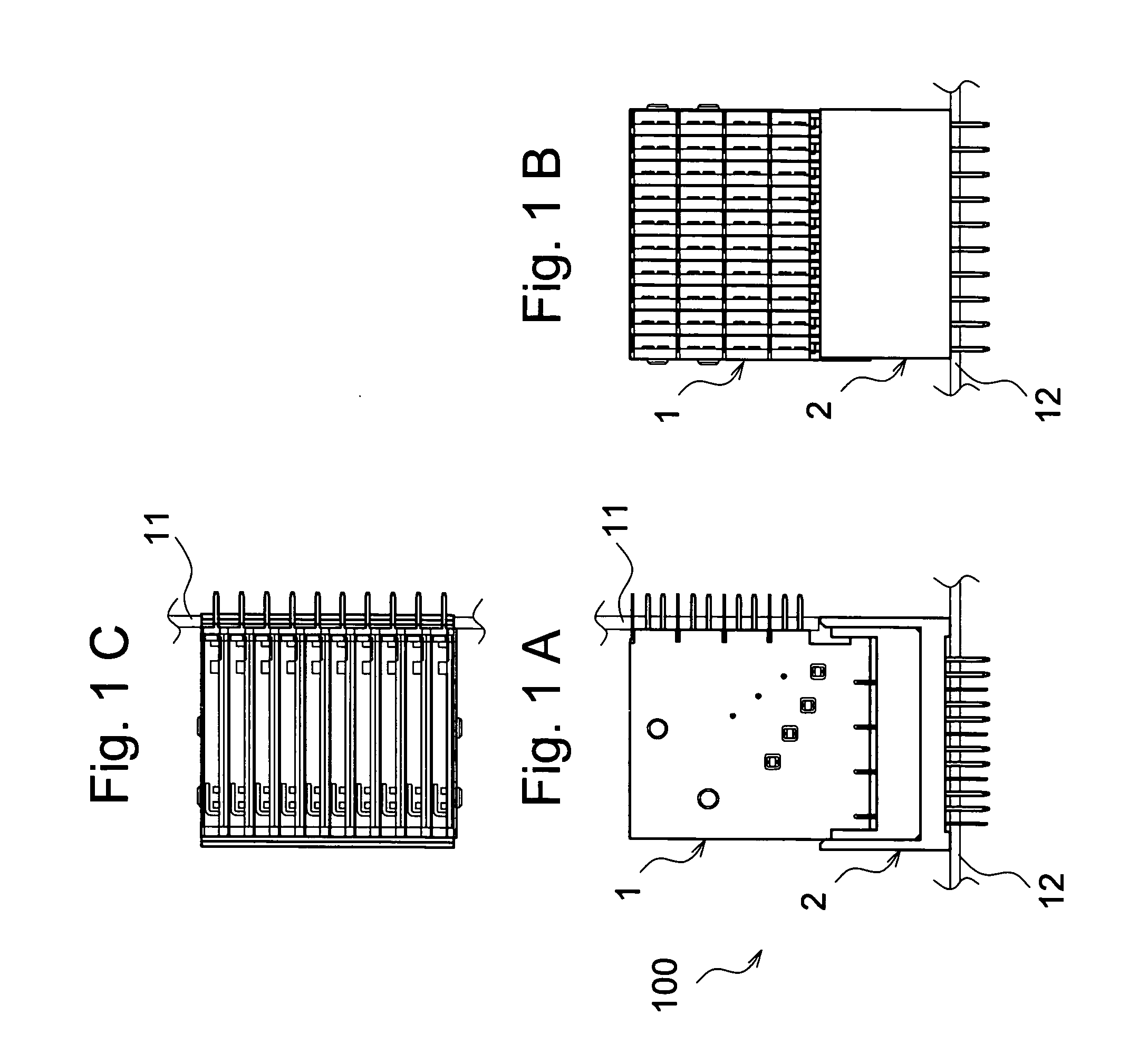
[0043]FIG. 1A is a front view of a transmission system to which a connector 100 in accordance with an embodiment of the present invention is applied. FIG. 1B is a side view of the transmission system. FIG. 1C is a plan view of the transmission system.

[0044] The transmission system includes a motherboard 12, a daughterboard 11 which is disposed perpendicular to this mother board, and a connector 100 which connects the motherboard 12 and the daughterboard 11.

[0045] The connector 100 includes plural stacked plug units 1 which are attached to a not-shown transmission path of the daughterboard 11 and a receptacle 2 to which the plug units 1 attached to a not-shown transmission path of the motherboard 12 are electrically connected.

[0046] Note that there are plural daughterboards. For example, a differential signal is sent from one daughterboard 11, and another daughterboard 11 receives this differential signal via the motherboard 12.

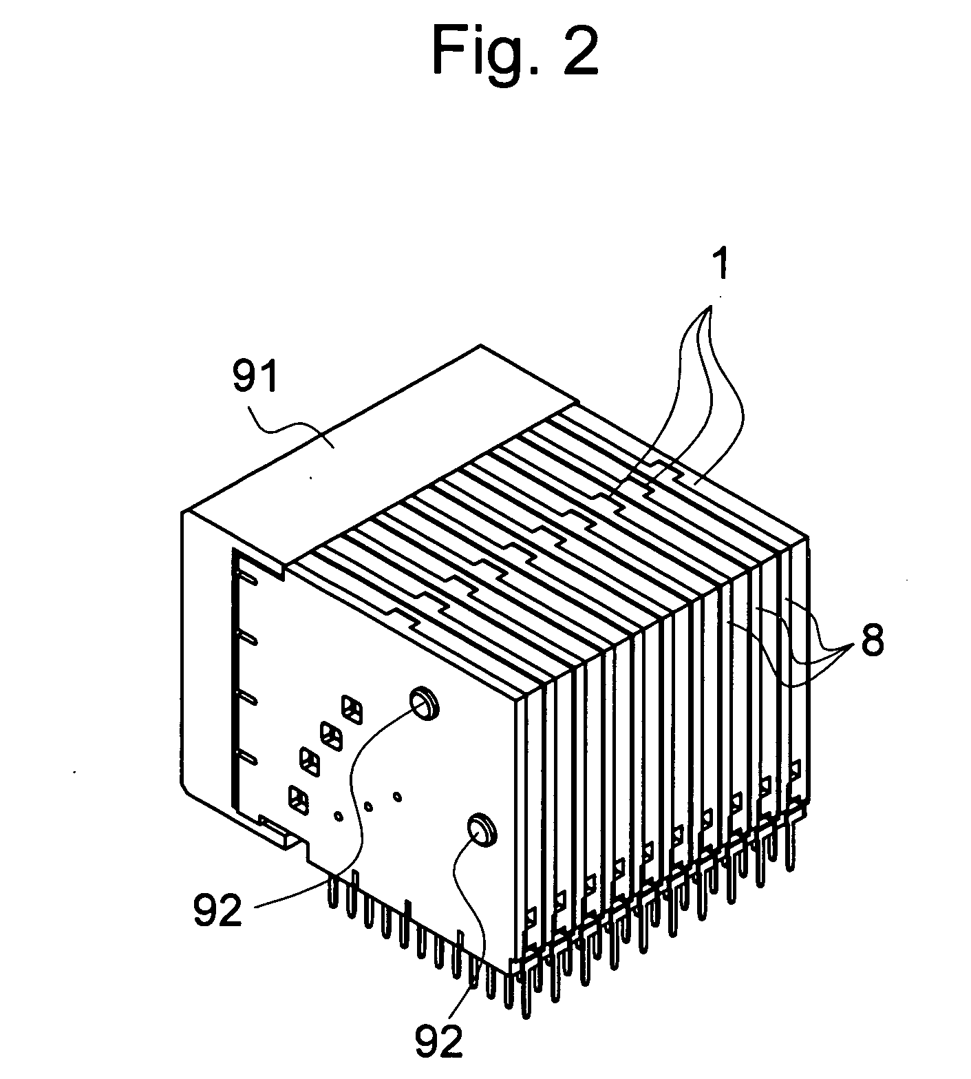
[0047]FIG. 2 is a perspective view showing a state i...


PUM


Abstract

The present invention relates to a connector which includes a plug unit and a receptacle. The plug unit includes a housing board and a transmission path board. The housing board has a housing board body and first connection terminals and second connection terminals. The transmission path board has a transmission path board body, plural differential signal patterns which are connected to the first connection terminals and the second connection terminals of the housing board, and high pass filters which are connected to each of the differential signal patterns. The receptacle has a receptacle body and pin contacts. According to the present invention, a low-frequency component of a digital signal is attenuated. Thus, since an attenuation factor of the high-frequency component and an attenuation factor of the low-frequency component of the digital signal can be set substantially the same, the digital signal can be transmitted surely.

Description

CROSS-REFERENCE TO RELATED APPLICATIONS [0001] This application is based upon and claims the benefit of priority from the prior Japanese Patent Application No. 2003-195330 filed on Jul. 10, 2003, the entire contents of which is incorporated herein by reference. FIELD OF THE INVENTION [0002] The present invention relates to a connector. In particular, the present invention relates to a connector which transmits signals between a daughterboard and a motherboard. BACKGROUND OF THE INVENTION [0003] Conventionally, there is known a connector which connects a daughterboard and a motherboard (e.g., see JP-A-7-6823). This connector includes a connector plug, which is attached to the daughterboard, and a connector receptacle in which this connector plug is fitted. This connector plug has a housing and plural transmission path blocks housed in this housing. These transmission path blocks are provided to be disposed at a predetermined interval. [0004] These transmission path blocks are planar....

Claims


Application Information

Patent Timeline
IPC IPC(8): H01R13/658H01R13/514H01R13/648H01R13/6587H01R13/719H01R13/7195
CPCH01R23/688H01R13/7195H01R13/6587
Inventor OTSU, AKIHIKOAZUMA, KEIICHITOKITA, HIROSHINAGASHIMA, NOBURO
Owner JST MFG CO LTD
Why Eureka
Try Eureka