
Medical laser treatment device

Inactive Publication Date: 2005-02-10
W&H DENTALWERK
View PDF6 Cites 31 Cited by
  • Summary
  • Abstract
  • Description
  • Claims
  • Application Information

AI Technical Summary

Benefits of technology

[0016] Solid state lasers, especially laser diodes, are particularly suitable for use as the first laser light source, while wafer lasers are particularly suitable for use as the second laser light source. A wafer laser has the advantage that the crystal which is used for the wafer laser can be cooled very effectively from virtually all sides. Since the diameter of the pump beam is generally very much larger than the thickness of the doped crystal wafer that is used, this greatly suppresses the formation of a so-called “thermal lens”, that is to say this avoids the possibility of different heating of the crystal resulting in changes, in particular distortion of the crystal which can lead to undesirable reflections, owing to the fact that the pump beam has a different intensity distribution, and generally has a Gaussian distribution.
[0017] Thus, in comparison to other laser systems, a wafer laser is also less susceptible to changes in the pump power, and its power is scalable while maintaining a constant good beam quality, which is particularly important fo

Problems solved by technology

At this point, it should be noted that the “starting up” of a pulsed laser light source generally requires at least 30 seconds, depending on the system, and in some circumstances more than one minute may pass before the pulsed laser light source is running in a stable manner, so that a perso

Method used


Image

  • Medical laser treatment device
  • Medical laser treatment device
  • Medical laser treatment device

Examples


Example

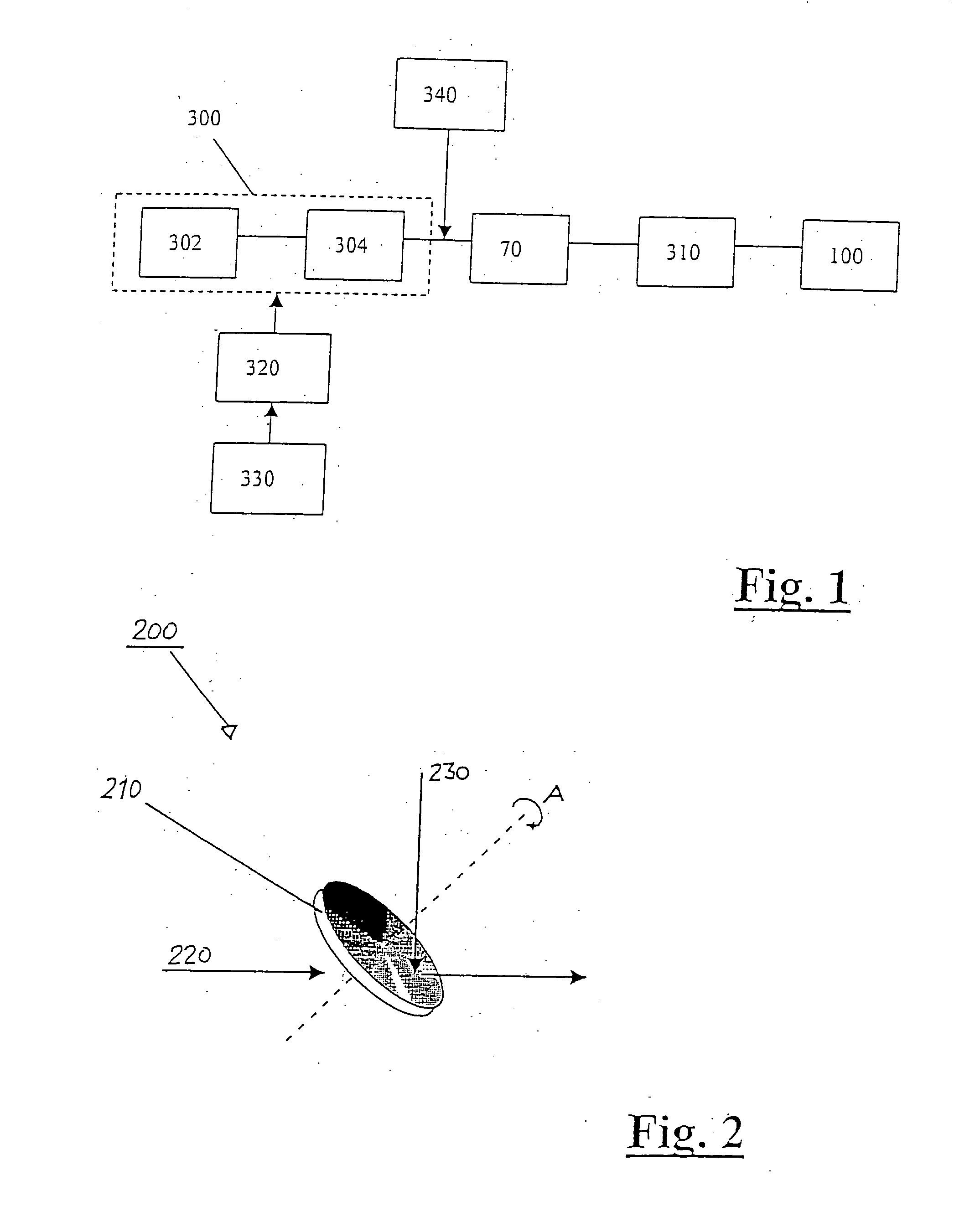
[0052]FIG. 1 shows, schematically and in the form of an overview illustration, a number of elements of one embodiment of a laser treatment appliance. The medical laser treatment appliance in this embodiment has laser light sources 302, which have a first laser light source comprising a number of laser diodes, and a wafer laser as the second laser light source, and an apparatus 304 for controlling the operating modes, which may also be assembled to form a combined laser unit 300.

[0053] The laser unit 300 or the laser light sources 302 and the apparatus 304 for controlling the operating modes are controlled via a control apparatus 320, which can in turn be operated by a switching apparatus 330, which can be operated by the person to be operated, generally a doctor or a technician.

[0054] The medical laser treatment appliance shown schematically in FIG. 1 also has an apparatus 340 for inputting an auxiliary laser beam, although it should be mentioned that this apparatus is purely opti...


PUM


Abstract

A medical laser treatment appliance which can be switched between a continuous wave (cw) operating mode and a pulsed operating mode and has at least one first laser light source for producing a cw laser beam, with the laser treatment appliance furthermore having a second laser light source for producing a pulsed laser beam, which is pumped by at least one first laser light sources, and the cw laser beam from at least one of first laser light sources is used for treatment in the cw operating mode, and the pulsed laser beam from the second laser light source is used for treatment in the pulsed operating mode, with the laser treatment appliance being designed such that the laser light source is also pumped continuously in the cw operating mode by at least one of the first laser light sources.

Description

[0001] The present invention relates to a medical laser treatment appliance having a laser light source, in particular a dentistry laser treatment appliance. BACKGROUND [0002] One such laser treatment appliance is known, for example, from DE 195 33 348 A1. In addition to the laser light source, such an appliance preferably has control elements, control apparatuses, apparatuses for carrying laser light, such as glass fiber cables or waveguides, as well as a hand piece, which forms a treatment instrument. Furthermore such laser treatment appliances may have power supply elements and displays or indicators, such as monitors or lamps, which are normally arranged or provided in housing elements. [0003] Medical laser treatment appliances are used for various medical purposes and in different embodiments. Depending on the purpose of use, the laser treatment appliances have to have different specifications, particularly with regard to the characteristic of the laser light which is emitted f...

Claims


Application Information

Patent Timeline
IPC IPC(8): A61B18/20A61C1/00A61C3/02A61N5/06H01S3/0941H01S3/23
CPCA61B18/20A61B2018/2065H01S3/2383H01S3/0604H01S3/09415A61C1/0046
Inventor BRUGGER, WILHELMKASENBACHER, ANTONNIEMZ, MARKBAUER, THORSTEN
Owner W&H DENTALWERK
Learn More