Exhaust gas purification device of internal combustion engine

a technology of exhaust gas purification and internal combustion engine, which is applied in the direction of exhaust treatment electric control, electrical control, separation process, etc., can solve the problems of low nosub>x /sub>purification rate, inability to obtain high nosub>x /sub>purification rate, and lower nosub>x /sub>purification rate, etc., to achieve the effect of higher nox purification ra

Inactive Publication Date: 2005-02-17
TOYOTA JIDOSHA KK
View PDF23 Cites 32 Cited by
  • Summary
  • Abstract
  • Description
  • Claims
  • Application Information

AI Technical Summary

Benefits of technology

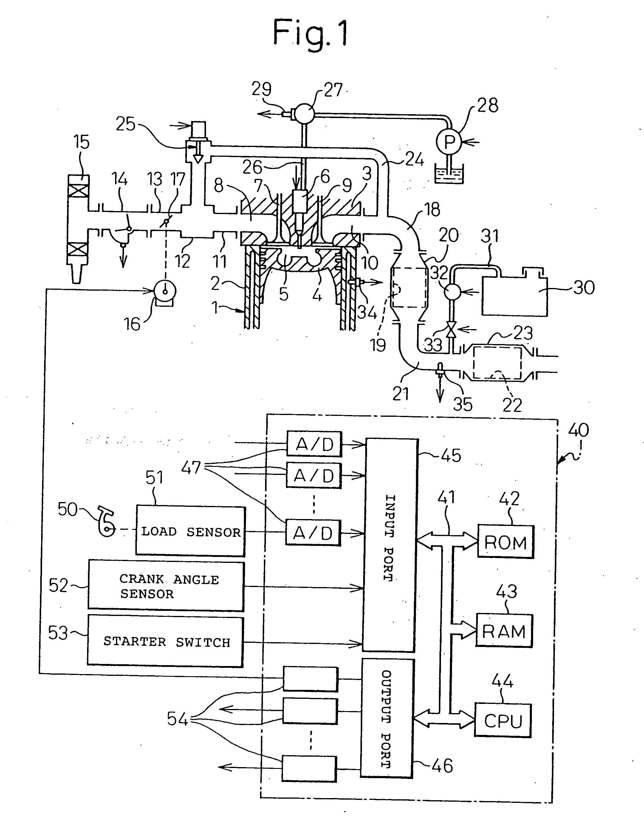
[0004] An object of the present invention is to provide an exhaust gas purification device of an internal combustion engine enabling the NOx purification rate to be made higher.
[0005] According to the present invention, there is provided an exhaust gas purification device of an internal combustion engine arranging a catalyst suitable for reduction of NOx in exhaust gas by ammonia in the presence of excess oxygen in an engine exhaust passage, the device comprising feeding means for feeding a liquid containing an ammonia generating compound to the catalyst and feed control means for controlling the amount of feed of the liquid, the catalyst storing inside it at least part of the ammonia generating compound contained in the liquid fed to the catalyst and having the function of causing the release of ammonia a little at a time from the ammonia generating compound stored in the catalyst along with the rise of temperature of the catalyst and redu

Problems solved by technology

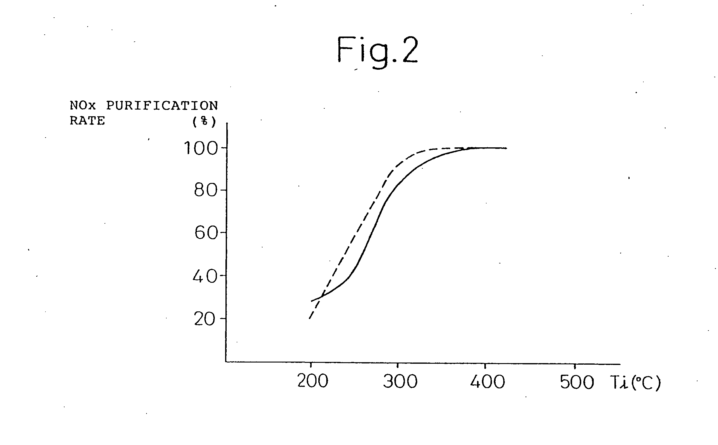
In this case, however, the purification rate of the NOx becomes lower along with a fall in the temperature of the catalyst.
So long as feeding urea by an equivalent ratio calculated in this way, however, when the catalyst temperature is not that high, the NOx purification rate is low.
Therefore, when the catalyst temperature is not that high, there is the problem th

Method used


Image

  • Exhaust gas purification device of internal combustion engine
  • Exhaust gas purification device of internal combustion engine
  • Exhaust gas purification device of internal combustion engine

Examples


first embodiment

[0064] Next, the feed control of an aqueous urea solution according to the present invention will be explained.

[0065] The amount of NOx discharged from the combustion chamber 5 per unit time increases along with an increase in the engine load. Therefore, as shown in FIG. 6A, the amount of NOx discharged from the combustion chamber 5 per unit time becomes greater the higher the temperature Ti of the exhaust gas flowing to the catalyst 22. Further, as shown in FIG. 6B, the amount of NOx discharged from the combustion chamber 5 per unit time is proportional to the amount Ga of intake air. Therefore, the amount QE of urea per unit time giving the equivalent ratio for the amount of NOx in the exhaust gas becomes a function of the temperature Ti of the exhaust gas and the amount Qa of the intake air. In this embodiment of the present invention, the amount QE of urea of the equivalent ratio to be fed per unit time is stored in advance in the ROM 42 in the form of a map as shown in FIG. 6C ...

second embodiment

[0086] Next, an explanation will be given of a second embodiment with reference to FIG. 14 and FIG. 15.

[0087] When the amount of feed of the aqueous urea solution is small, the aqueous urea solution disperses in the exhaust gas. If the aqueous urea solution disperses in the exhaust gas, the urea in the aqueous urea solution will easily decompose by the heat and as a result it will become difficult to store the urea fed in the catalyst 22. As opposed to this, if the amount of feed of the aqueous urea solution is increased, the density of the urea in the exhaust gas will become higher and as a result the urea will become harder to decompose by heat, so the urea fed will be able to be stored in the catalyst 22.

[0088] Therefore, in the second embodiment, as shown in FIG. 14, in the operation region I, operation region II, and at the time of deceleration, the aqueous urea solution is fed so that the amount of urea to be fed becomes the amount of urea of the equivalent ratio, the urea is...

third embodiment

[0095] Next, an explanation will be given of a third embodiment while referring to FIG. 16 and FIG. 17.

[0096] When the temperature of the exhaust gas is low, the amount of NOx in the exhaust gas becomes extremely small. Therefore, in this third embodiment, when the temperature Ti of the exhaust gas flowing into the catalyst 22 is lower than a predetermined value T0, for example, 132° C., the continuous feed of the aqueous urea solution is stopped and, as shown in FIG. 16, in the operation region I and at the time of deceleration, large amounts of aqueous urea solution are fed in pulses at time intervals to make the urea in the aqueous urea solution be stored in the catalyst 22.

[0097] Note that in the third embodiment as well, the routine shown in FIG. 10 is used, but the routine shown in FIG. 17 is used only for step 103 of FIG. 10.

[0098] Referring to FIG. 17, first, at step 400, it is determined if the feed stop flag indicating that the feed of the aqueous urea solution should be...


PUM

PropertyMeasurementUnit
Temperatureaaaaaaaaaa

Abstract

A catalyst (22) suitable for reduction of the NOx in an exhaust gas by ammonia in the presence of excess oxygen is arranged in the exhaust passage (18, 21) of an internal combustion engine. An aqueous urea solution is fed through a flow control valve (33) to the inside of the exhaust passage (21) upstream of the catalyst (22). When the temperature of the catalyst (22) is low, a large amount of the aqueous urea solution is fed to make the urea contained in the aqueous urea solution be stored in the catalyst (22). When the engine is accelerated and the temperature of the catalyst (22) rises, ammonia is released at a little at a time from the inside of the catalyst (22) and the NOx in the exhaust gas is reduced by the released ammonia.

Description

TECHNICAL FIELD [0001] The present invention relates to an exhaust gas purification device of an internal combustion engine. BACKGROUND ART [0002] It is possible to place a catalyst suitable for the reduction of NOx in an exhaust gas by ammonia and to feed an aqueous urea solution into the engine exhaust passage upstream of the catalyst to cause reduction of the NOx in exhaust gas by the ammonia generated from the aqueous urea solution. In this case, however, the purification rate of the NOx becomes lower along with a fall in the temperature of the catalyst. Therefore, known in the art has been an internal combustion engine designed to calculate the equivalent ratio of the urea necessary for reducing NOx by an NOx purification rate in accordance with the catalyst temperature and to control the amount of feed of the aqueous urea solution so that urea is fed by that equivalent ratio (see Japanese Unexamined Utility Model Publication (Kokai) No. 3-129712). [0003] So long as feeding ure...

Claims


Application Information

Patent Timeline
IPC IPC(8): F01N3/08B01D53/90B01D53/94C01B21/00F01N3/00F01N3/10F01N3/20F01N3/24F01N3/28F01N11/00F01N13/02F01N13/04F02D21/08F02D41/00F02D41/02F02D41/12F02M25/06F02M25/07
CPCB01D53/90F01N13/011B01D53/9431B01D53/9495B01D2251/2062F01N3/2053F01N3/206F01N3/2066F01N3/208F01N11/002F01N2250/12F01N2510/063F01N2510/0682F01N2560/06F01N2570/14F01N2570/18F01N2610/02F01N2610/146F01N2900/08F01N2900/1402F01N2900/1622F02D35/025F02D41/0055F02D41/0235F02D41/123F02D41/1446F02D2200/0602F02D2200/0802F02M25/0715F02M25/0718Y02T10/47Y02T10/24F01N13/0097F01N13/0093F01N13/009B01D53/9409F02M26/13F02M26/15Y02T10/12Y02T10/40Y02A50/20F01N3/20
Inventor ITOH, KAZUHIROTANAKA, TOSHIAKIIWASAKI, EIJIHIROTA, SHINYA
Owner TOYOTA JIDOSHA KK
Why Eureka
Try Eureka