
Sensor comprising mechanical amplification of surface stress sensitive cantilever

a technology of stress sensitive cantilever and sensor, which is applied in the field of sensors, can solve problems such as deflection and/or stretch, and achieve the effect of preventing short-circuiting of electrical connections during operation

Inactive Publication Date: 2005-02-17
CANTION
View PDF13 Cites 28 Cited by
  • Summary
  • Abstract
  • Description
  • Claims
  • Application Information

AI Technical Summary

Benefits of technology

[0040] The piezoresistive element is normally partly integrated or protrudes into the substrate where it is connected to two wires. The piezoresistive element may in one embodiment have an extension into the piezoresistive cantilever to a distance from the substrate connection line which is 80% or less, such as 50% or less, such as 30% or less of the length of the protruding cantilever. By providing the piezoresistive cantilever with a high flexibility in areas of the cantilever where it contains the piezoresistive element, an increased signal may be obtained.
[0043] In one embodiment the poly-cantilever comprises two or more capture surface cantilevers, thereby an even higher signal may be obtained.
[0045] In one embodiment where the piezoresistive cantilever do not comprise a capture surface, the piezoresistive element need not be insulated even if used in detecting of a target substance in a liquid, because the piezoresistive cantilever do not need to come into contact with the liquid. Thereby the sensor may be much more simple to produce because steps of insulating the piezoresistive element may be omitted.

Problems solved by technology

The mechanical compression or decompression may result in a deflection and / or a stretch.

Method used


Image

  • Sensor comprising mechanical amplification of surface stress sensitive cantilever
  • Sensor comprising mechanical amplification of surface stress sensitive cantilever
  • Sensor comprising mechanical amplification of surface stress sensitive cantilever

Examples


Embodiment Construction

[0063] Embodiments of the invention will be described further with reference to the figures.

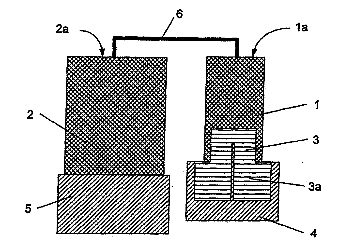
[0064]FIG. 1 is a schematic illustration of first poly-cantilever shown as a sectional top cut.

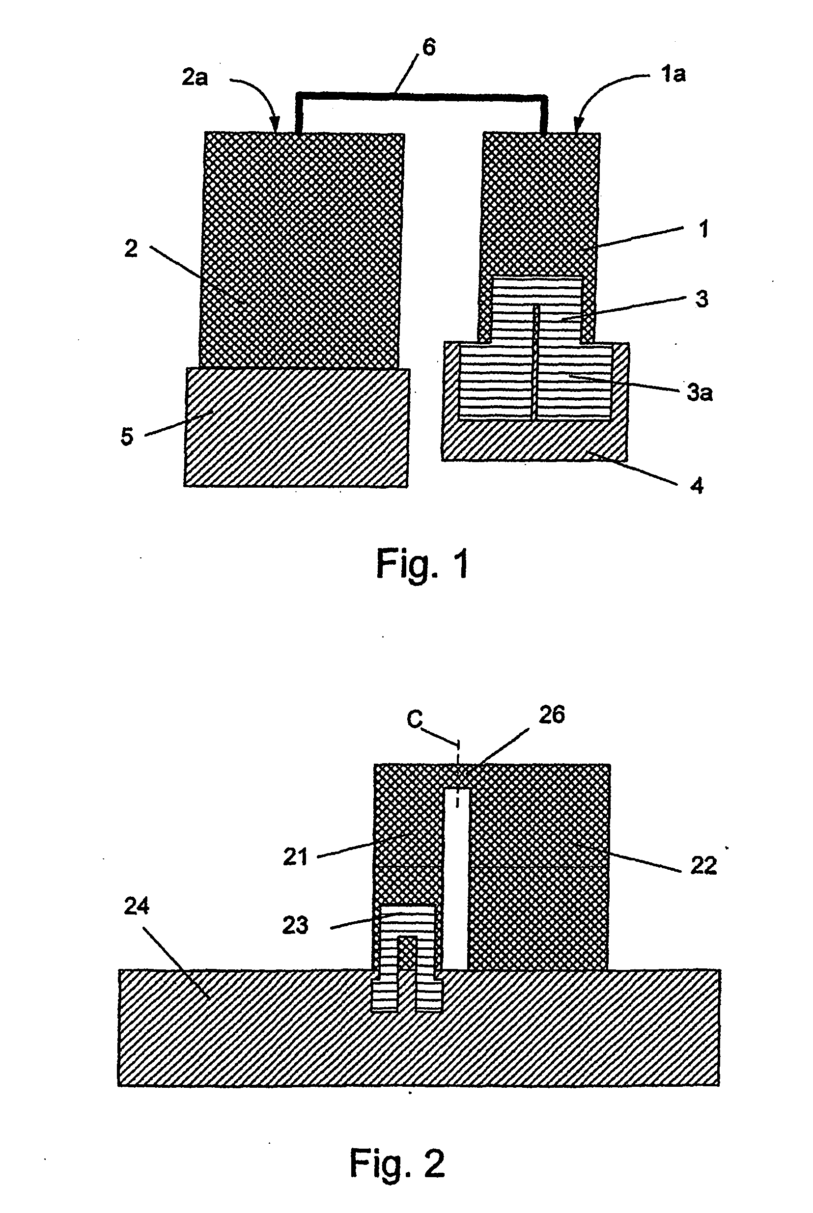
[0065]FIG. 2 is a schematic illustration of second poly-cantilever shown as a sectional top cut.

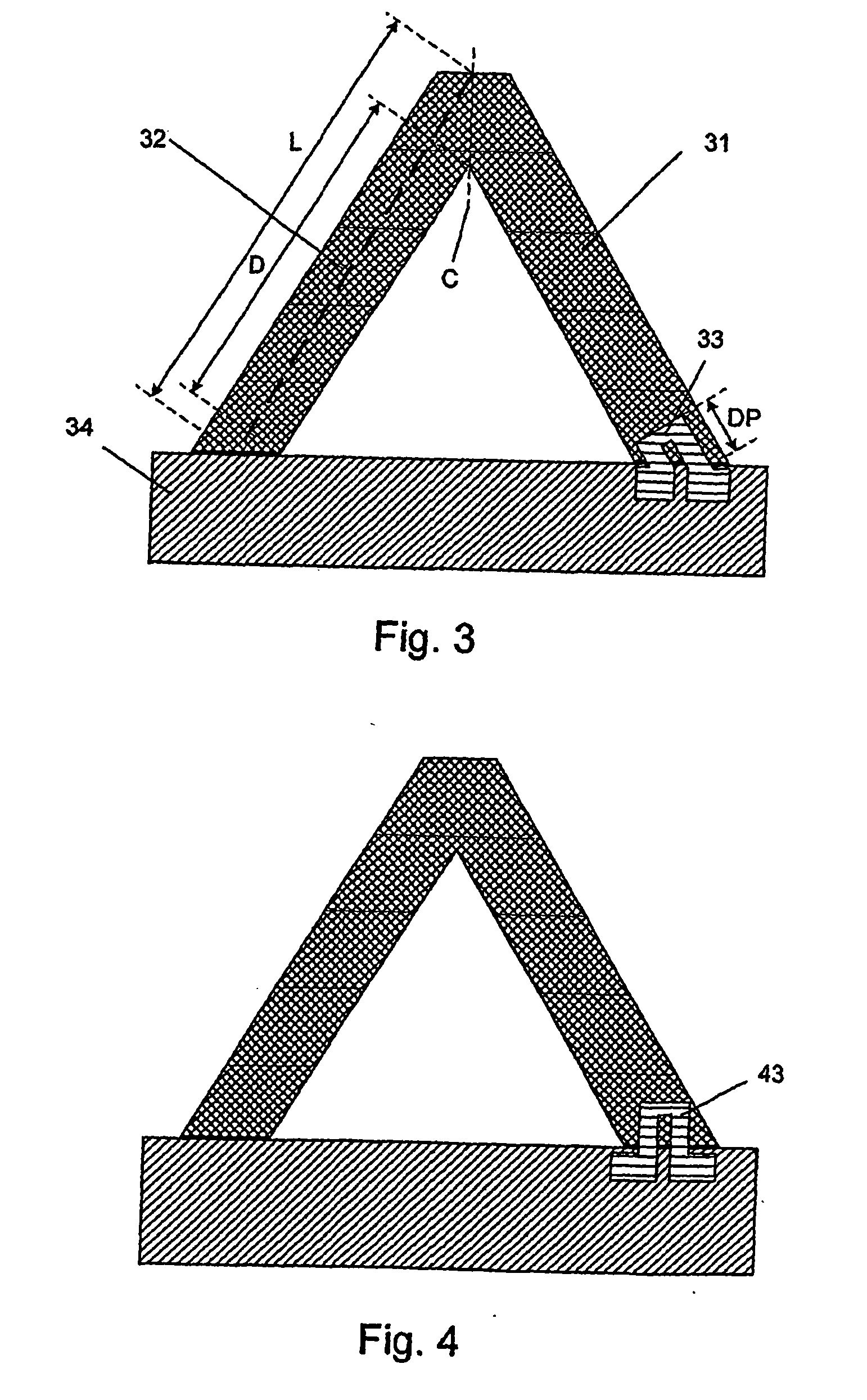
[0066]FIG. 3 is a schematic illustration of third poly-cantilever shown as a sectional top cut.

[0067]FIG. 4 is a schematic illustration of fourth poly-cantilever shown as a sectional top cut. The fourth poly-cantilever is a variation of the poly-cantilever shown in FIG. 3.

[0068]FIG. 5 is a schematic illustration of fifth poly-cantilever shown as a sectional top cut.

[0069]FIG. 6 is a schematic illustration of sixth poly-cantilever shown as a sectional top cut. The sixth poly-cantilever is a variation of the poly-cantilever shown in FIG. 5.

[0070]FIG. 7 is a schematic illustration of seventh poly-cantilever shown as a sectional top cut.

[0071]FIG. 8 is a schematic illustration of eighth poly-cantileve...


PUM


Abstract

The invention relates to a sensor comprising one or more sensor units, wherein at least one of the sensor units is in the form of a poly-cantilever structure. The poly-cantilever structure comprise two or more cantilever-like structures, at least one of the cantilever-like structures comprises a piezoresistive element, and at least one of the cantilever-like structures comprises a capture surface, at least one cantilever-like structure with a piezoresistive element designated a piezoresistive cantilever being connected in an amplifying connection to at least one of the cantilever-like structure with a capture surface designated a capture surface cantilever. The amplifying connection being provided so that a deflection of said capture surface cantilever due to a stress generated at said capture surface being capable of deflecting the connected piezoresistive cantilever. The sensor can be used for detection of a target substance in a fluid, such as a gas or a liquid.

Description

FIELD OF THE INVENTION [0001] The present invention relates to a sensor comprising one or more sensor units, wherein each sensor units comprises a capture surface area and a piezoresistive detection system, for direct detection of stress change of the sensor unit. One type—the most commonly used type of sensor unit—is a cantilever. BACKGROUND OF THE INVENTION [0002] In the art of detecting components in fluids, cantilever based sensors with integrated piezoresistors are used as very sensitive mechanical stress sensors. As described in e.g. WO 0066266 and WO 9938007, micro cantilevers can be used for detection of molecular interaction. At least one surface of the cantilever is coated with a capture layer, which capture layer reacts with a target molecule of interest. If the cantilever is exposed to a sample in which the target molecule is present, the target molecule will react with the capture molecule on the cantilever surface and a surface stress change will be generated. [0003] D...

Claims


Application Information

Patent Timeline
IPC IPC(8): G01L1/18G01N33/543
CPCG01N33/5438G01L1/18G01N33/48707
Inventor THAYSEN, JACOB
Owner CANTION
Learn More