Apparatus for transferring loose material

Inactive Publication Date: 2005-02-17
VIMA IMPIANTI
View PDF13 Cites 8 Cited by
  • Summary
  • Abstract
  • Description
  • Claims
  • Application Information

AI Technical Summary

Benefits of technology

[0016] The aim of the present invention is to provide an apparatus for transferring loose material which is free of the disadvantages listed above and which is, at the same time, functional, easy and economical to make and practical and effective to use.

Problems solved by technology

Diffusion of the powders in the environment must be contained as far as possible, above all if the powders consist of chemical compounds or substances that are not easily degradable in the environment and / or constitute a potential health risk.
An important problem is the possibility that the loose material, as it passes from the upper container to the lower tank through the above-mentioned flexible pipe, which is normally very long, may lose its homogeneity due to separation of its components.
This disadvantage is particularly bad when the material consists of powders; indeed, separation or demixing of the various components of which the powders are constituted may easily occur when a significant mass of powder rapidly falls along the flexible pipe.
Another disadvantage linked to rapid passage through the flexible pipe is the possibility that pellets or tablets may deteriorate due to the excessive speed reached at the end of the pipe.
Although they guarantee good operation, the known solutions described above are not without disadvantages.
A first disadvantage of the above-mentioned known solutions is the fact that both are characterized by large dimensions in the portion of the system between the upper container and the lower tank.
Another disadvantage is the extreme structural complexity of the known systems, which also require complicated control and command apparatuses for their management.

Method used


Image

  • Apparatus for transferring loose material
  • Apparatus for transferring loose material
  • Apparatus for transferring loose material

Examples


Embodiment Construction

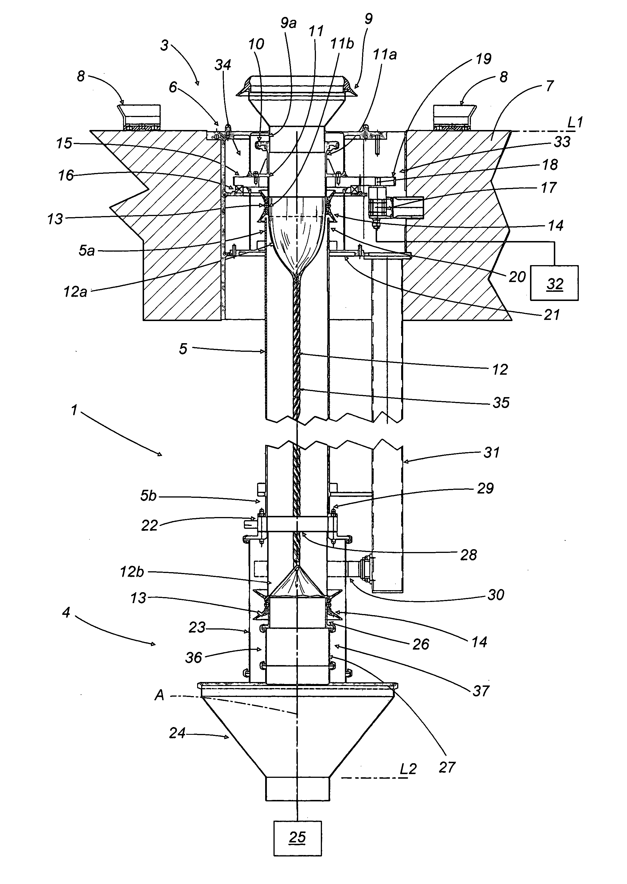
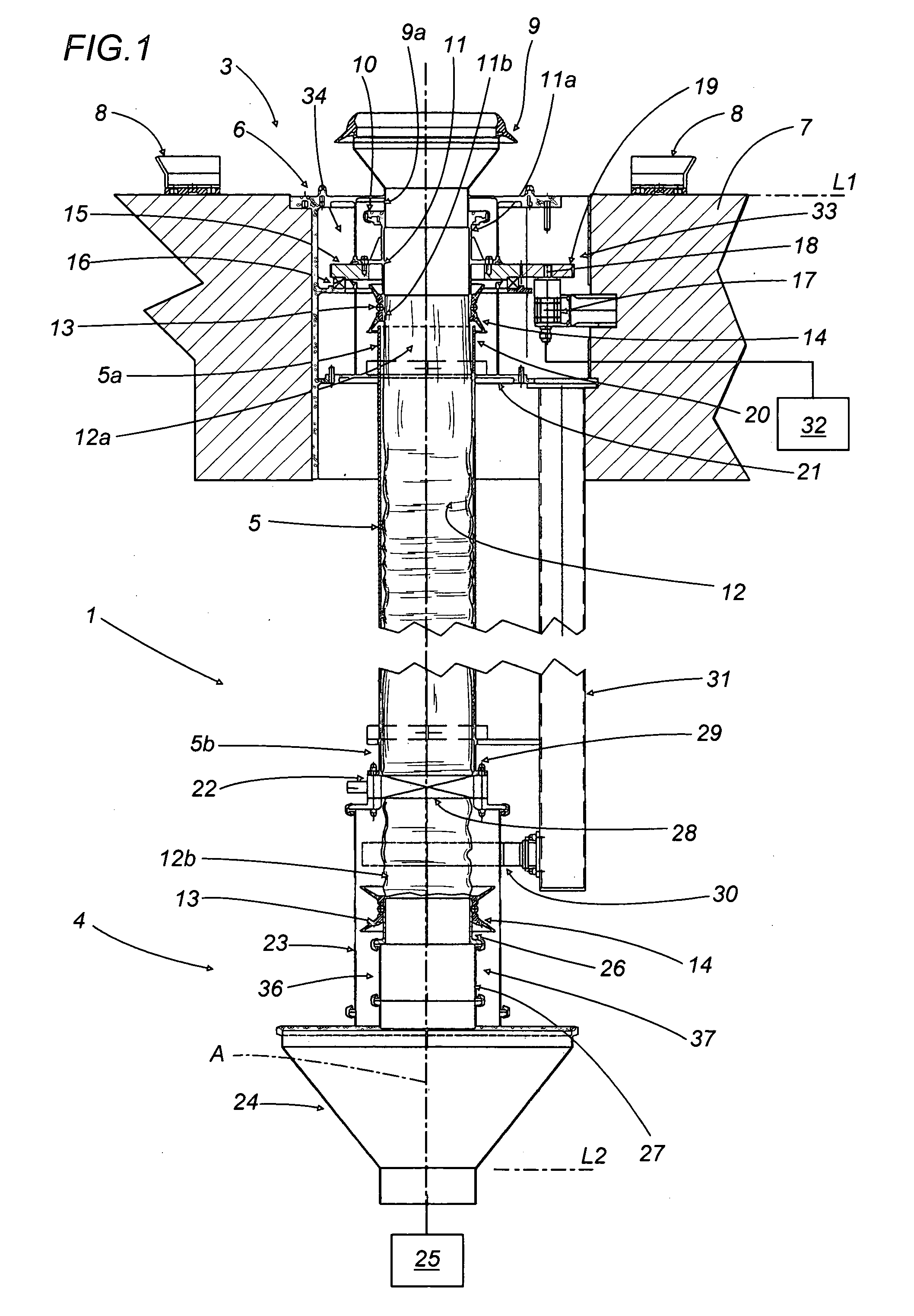
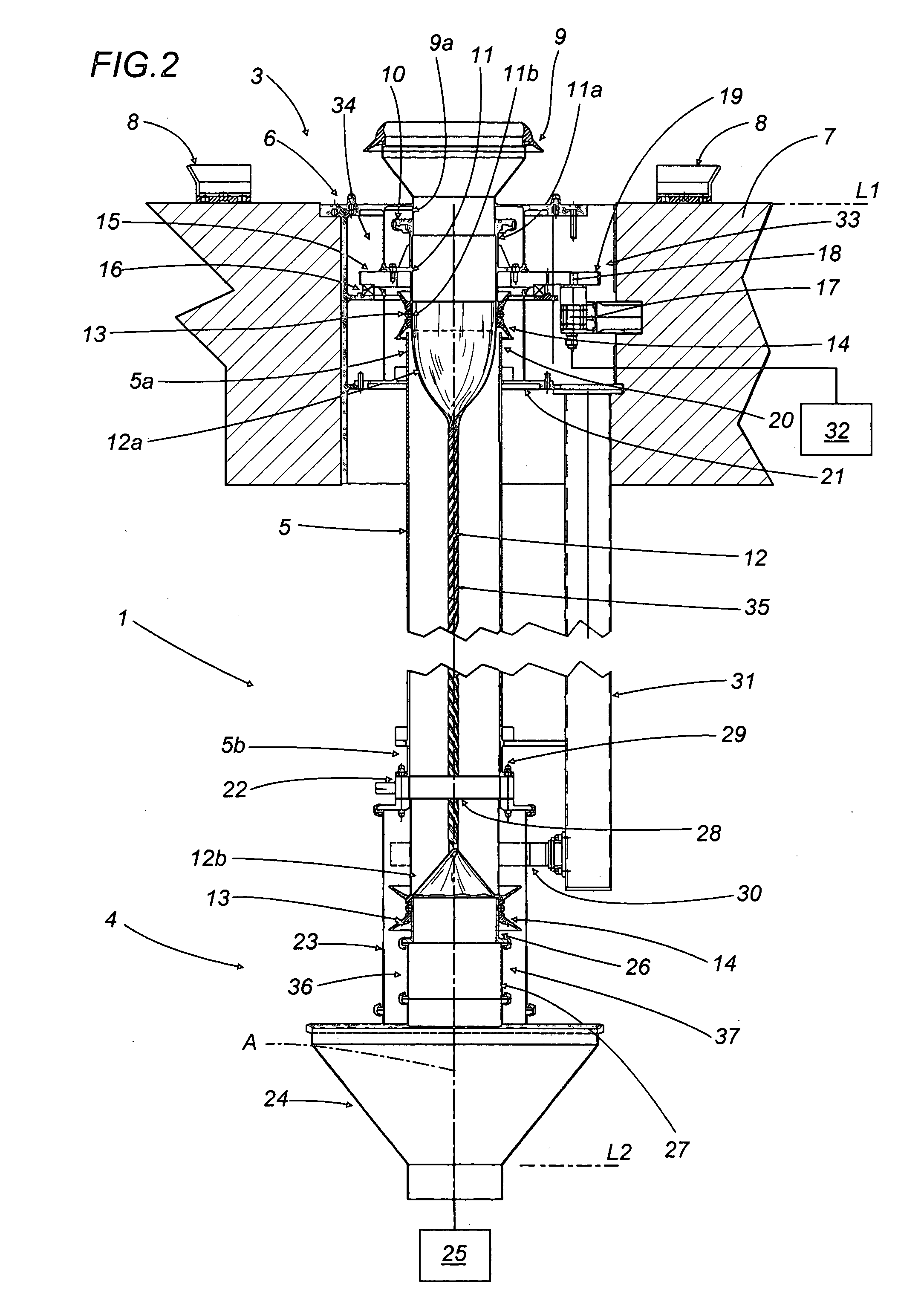
[0021] With reference to the accompanying drawings, the numeral 1 denotes as a whole an apparatus for transferring a loose material 2 from a station 3 for unloading a container not illustrated to a receiving station 4.

[0022] The unloading station 3 is located at a first, upper level L1 and the receiving station 4 is located at a second, lower level L2.

[0023] A rigid pipe 5, advantageously made of polycarbonate or other transparent material, connects the stations 3 and 4 extending vertically along its central axis A.

[0024] The apparatus 1 comprises a supporting structure 6 connected to a portion 7 of a floor made of brickwork or other material.

[0025] The accompanying drawings illustrate a non-limiting example in which there is a difference in the height of a material unloading station and a relative receiving station and in which the material is basically transferred by gravity.

[0026] At the first level L1 the structure 6 comprises a cup 8 for positioning a container, not illust...


PUM

PropertyMeasurementUnit
Lengthaaaaaaaaaa
Flexibilityaaaaaaaaaa
Gravityaaaaaaaaaa

Abstract

The apparatus for transferring loose material from an unloading station located at a first, upper level to a receiving station located at a second, lower level, comprises a flexible pipe for the passage of the loose material, the pipe having an axis of extension and a first end connected to the unloading station and a second end connected to the receiving station.

Description

BACKGROUND OF THE INVENTION [0001] The present invention relates to an apparatus for transferring loose material. [0002] In particular, the present invention relates to an apparatus which can be used in the chemical and / or pharmaceutical and / or food sector and in any other sector which requires the unloading of containers holding loose material, consisting of powders, pellets, tablets, capsules or similar products. [0003] The above-mentioned containers are emptied at an unloading station, located at an upper level, the material contained in the containers is transferred from the unloading station to a collection station located at a lower level. The collection station comprises a receptacle, for example a tank or hopper connected to a treatment unit where the loose material is subject to subsequent processing. [0004] The height difference between the above-mentioned levels is such that it allows the container to be emptied by the action of gravity. [0005] For the loose material to f...

Claims


Application Information

Patent Timeline
IPC IPC(8): B65B39/02B65B69/00B65G65/40B65G69/16B65G69/18
CPCB65B39/02B65G69/181B65G69/16B65B69/0075
Inventor BONITA, ANTONIO
Owner VIMA IMPIANTI
Why Eureka
Try Eureka