Device for material and/or energy exchange in a wash column

a technology of material and/or energy exchange, which is applied in the direction of feed devices, mixing methods, combustion air/fuel air treatment, etc., can solve problems such as poor distribution

Inactive Publication Date: 2005-02-17
MANTEUFEL ROLF P C
View PDF11 Cites 15 Cited by
  • Summary
  • Abstract
  • Description
  • Claims
  • Application Information

AI Technical Summary

Benefits of technology

[0011] The stability of the contact points is better enabled in a special embodiment, in that two or more vertical, wavy wires are arranged one directly next to the other. Then, the warp wire of an adjacent fabric or grid web can come to lie with its bulge between the bulges of the double wire of the adjacent fabric or grid web, which creates a stable position. With individual wires the position can be unstable, when the bulges lying against to each other tend to slide off their opposing peak points. Another possibility for increasing the stability is the arrangement of fabric or grid webs with warp wires lying one directly next to the other alternating with webs in which the warp wires are present individually. In this way, the individual warp wires each come to lie between the bulges of the warp wires lying directly next to each other in adjacent webs, whereby a stable position is likewise achieved.
[0023] In the discharge channels, horizontal perforated sheets with laterally running slots or fabric are attached, which supply the liquid flowing through the supply tubes to the individual wires of the webs from below. In this way, a uniform liquid distribution is assured. The perforated sheets can serve simultaneously for clamping the wires suspended in the discharge channels.

Problems solved by technology

Any amount of shift means poor distribution, wherein a deviation of ±50% among the individual trickling amounts leads to a doubling of the necessary exchange surface, and with larger deviations the exchange surface has practically no more effect on the separating performance.

Method used


Image

  • Device for material and/or energy exchange in a wash column
  • Device for material and/or energy exchange in a wash column
  • Device for material and/or energy exchange in a wash column

Examples


Embodiment Construction

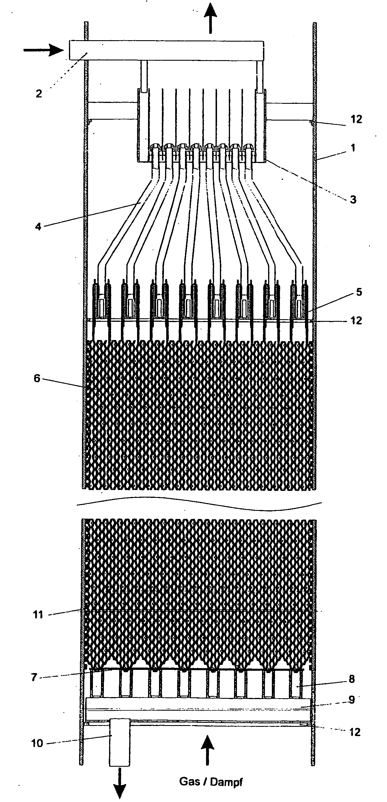
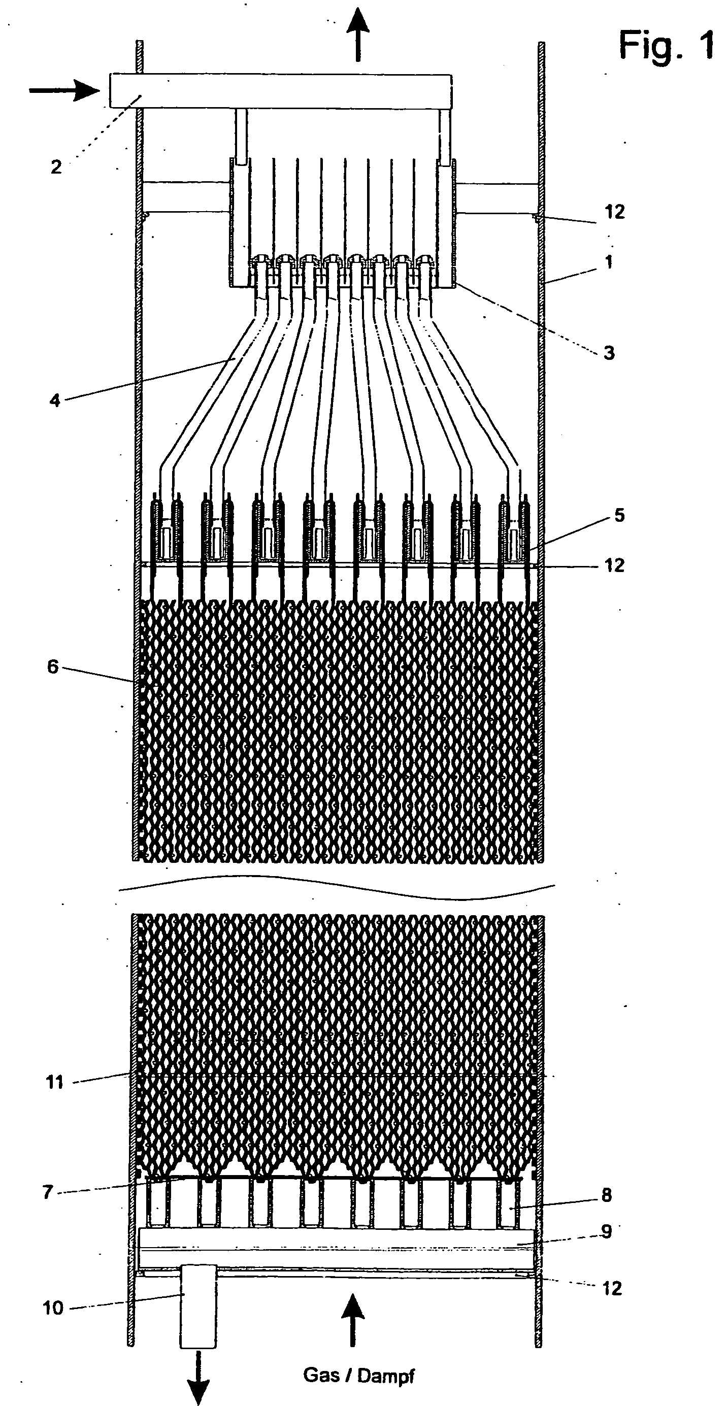
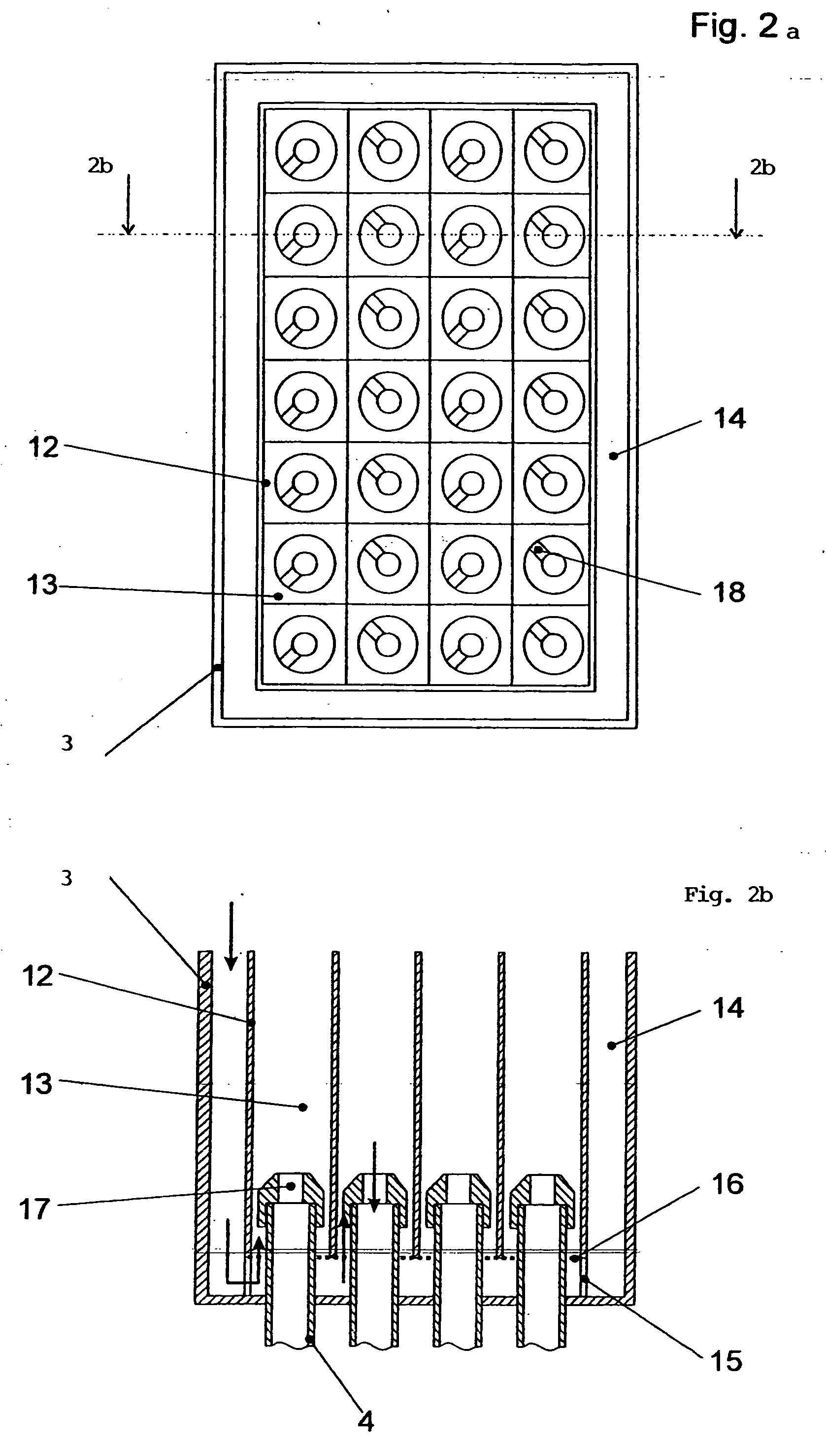
[0039] As an example, FIG. 1 shows the installation of the device in a cylindrical container 1 (column). The liquid enters through a supply tube 2 into the device and is fed through tubes into the distributor head 3. This distributes the liquid through the system shown in FIG. 3 uniformly to the supply tubes 4, which end in the distributor channels 5. Suspended on these channels is a packet made from fabric webs 6 arranged next to one another. The liquid is output from the channels 5 uniformly onto the fabric webs and guided downwardly on these webs.

[0040] The individual fabric webs are arranged next to one another, such that they are in contact at the wave peaks of the vertical wires and thus the liquid can transfer from web to web. The length of the webs can be adapted for the respective application purpose. At the lower end the block composed of fabric webs stands on a holder profile 7, which is fixed on several horizontally running discharge channels 8. The liquid trickling dow...


PUM

PropertyMeasurementUnit
thicknessesaaaaaaaaaa
widthaaaaaaaaaa
widthaaaaaaaaaa

Abstract

A device for maximum vapor or gas throughput is provided for material and / or energy exchange, in which large vertical flow spaces are present. Vapors or gases flow without impact losses and thus with extremely low pressure loss per meter in counter flow to liquid on zigzag wires or threads arranged vertically next to one another, produced with conventional web or braiding machines, along wide-meshed fabric or grid webs and are brought for exchange with the liquid. Simultaneously, by optimizing the wire or thread diameter and its count and the arrangement of fabric or grid webs, considering the large vertical flow spaces and a uniform wetting of the large number of zigzag wires or threads arranged vertically next to one another against the wave peaks, a minimal specific volume of the device is achieved by wide-meshed fabrics or grids for the vapor or gas flow through a step-wise division of the trickling liquid.

Description

CROSS-REFERENCE TO RELATED APPLICATIONS [0001] This application is a continuation of International Application No. PCT / EP02 / 14612, filed Dec. 20, 2002, and the disclosure of which is incorporated herein by reference.BACKGROUND OF THE INVENTION [0002] The invention relates to a device for the exchange of material and / or energy in a wash column, wherein three-dimensional wire or thread packing in a form of at least one group of wide-meshed fabrics or grids is arranged in parallel in the column. [0003] For optimum benefit in using such a device, the phases to be exchanged must be fed in counter flow with the largest possible phase contact or boundary surface and the smallest possible energy loss (≢p / m). A large phase boundary surface can be achieved by providing a large number of wires or threads guided vertically through the device, wherein the liquid running down these wires or threads is constantly replaced and is located in direct counter flow to the rising phase. [0004] Here, the ...

Claims


Application Information

Patent Timeline
Patent Type & Authority Applications(United States)
IPC IPC(8): B01D3/00B01D53/18B01J4/00B01J19/32
CPCB01D3/008B01D53/185B01J4/001B01J19/32B01J2219/3221B01J2219/3325B01J2219/32227B01J2219/32286B01J2219/32289B01J2219/32466B01J2219/32491B01J2219/32213
Inventor MANTEUFEL, ROLF P.C.
Owner MANTEUFEL ROLF P C
Why Eureka
Try Eureka