Projector having improved structure for cooling optical system

a technology of optical system and projector, which is applied in the field of projectors, can solve the problems of heating and damage of components inside the optical system, and achieve the effects of reducing noise, preventing energy waste, and efficiently cooling some components

Inactive Publication Date: 2005-02-17
SAMSUNG ELECTRONICS CO LTD
View PDF6 Cites 17 Cited by
  • Summary
  • Abstract
  • Description
  • Claims
  • Application Information

AI Technical Summary

Benefits of technology

[0018] Accordingly, it is an aspect of the present invention to provide a projector in which a guiding duct is partitioned so that cool air is distributed according to whether the cool air is sent to a relatively high temperature place or a relatively low temperature place in an optical system, therefore preventing wasting of energy by efficiently cooling some components of the optical system without overcooling others, and reducing noise due to the rotation of a cooling fan and air flow.

Problems solved by technology

This heat may cause components inside the optical system to be heated and damaged.

Method used


Image

  • Projector having improved structure for cooling optical system
  • Projector having improved structure for cooling optical system
  • Projector having improved structure for cooling optical system

Examples


Embodiment Construction

[0032] Reference will now be made in detail to the embodiments of the present invention, examples of which are illustrated in the accompanying drawings, wherein like reference numerals refer to like elements throughout. The embodiments are described below in order to explain the present invention by referring to the figures.

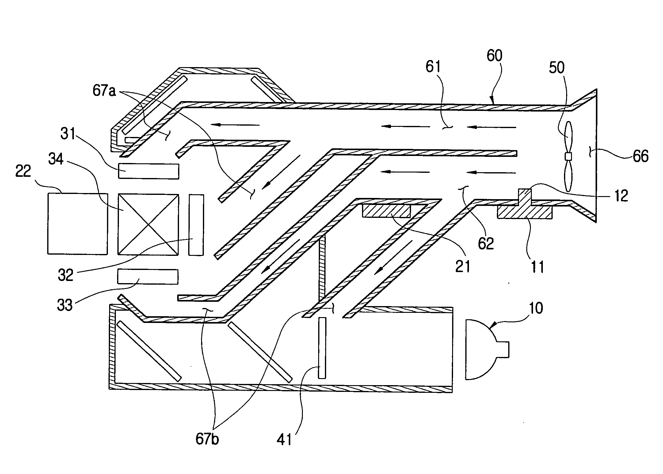
[0033] As shown in FIGS. 3 and 4, a projector according to an embodiment of the present invention includes a lamp 10 used as a light source, an optical synthesizer 30 synthesizing a picture, an optical system 20 including optical components 40 disposed along an optical path from the lamp 10 to the optical synthesizer 30, a printed circuit board (PCB) 21 driving the optical system 20, a lamp driving circuit 11 driving the lamp 10, a cooling fan 50 generating cool air for cooling the optical system 20, and a guiding duct 60 to guide the cool air to be distributed into a first passage 61 and a second passage 62.

[0034] The lamp 10 includes a high-power lamp such as...


PUM


Abstract

A projector projecting an image onto a screen, comprises a lamp emitting light; an optical system having an optical synthesizer including a blue panel, a green panel and a red panel, and an optical component disposed along an optical path from the lamp to the optical synthesizer; a cooling fan generating cool air cooling the optical system; and a guiding duct guiding the cool air to be distributed into a first passage and a second passage. With this configuration, the present invention provides a projector in which a guiding duct is partitioned and therefore cool air is distributed according to whether the cool air is sent to a relatively high temperature place or a relatively low temperature place in an optical system, preventing energy from being wasted by efficiently cooling some components of the optical system without overcooling others, and reducing noise caused by a cooling fan and air flow.

Description

CROSS-REFERENCE TO RELATED APPLICATIONS [0001] This application claims the benefit of Korean Patent Application No. 2003-55446, filed Aug. 11, 2003, in the Korean Intellectual Property Office, the disclosure of which is incorporated herein by reference. BACKGROUND OF THE INVENTION [0002] 1. Field of the Invention [0003] The present invention relates to a projector for projecting an image onto a screen, and more particularly, to a projector having an improved structure for cooling an optical system thereof. [0004] 2. Description of the Related Art [0005] A projector is a device generally including a light source and an optical system projecting and enlarging an image onto a screen, and is divided into two types, a CRT (Cathode Ray Tube) type and an LCD (Liquid Crystal Display) type. [0006] The CRT-type projector (hereinafter referred to as a “CRT projector”) comprises a CRT assembly projecting an image beam, a mirror reflecting the projected beam, and a screen on which the reflected ...

Claims


Application Information

Patent Timeline
Patent Type & Authority Applications(United States)
IPC IPC(8): G03B21/14G03B21/00G03B21/16G03B21/18G03B21/26
CPCG03B21/18G03B21/14
Inventor KIM, SRUHUR, JEAN
Owner SAMSUNG ELECTRONICS CO LTD
Why Eureka
Try Eureka