Vehicular radar device

Active Publication Date: 2005-02-17
OMRON AUTOMOTIVE ELECTRONICS CO LTD
View PDF9 Cites 15 Cited by
  • Summary
  • Abstract
  • Description
  • Claims
  • Application Information

AI Technical Summary

Benefits of technology

[0035] Namely, it is possible to adopt a construction in which the rain decision time or the road surface decision time is a time at which when a target decision based on a feature quantity of a received waveform is performed on the detection data obtained through the detection operation in the normal state, the result of the target decision shows that there exists detection data presumed to be relative to the road surface or rain or the like. In this case, there is the advantage that a decision based on a shift of the visual field is made only when necessary and a decision as to the road surface or rain or the like is efficiently exe

Problems solved by technology

However, the above-mentioned related arts have the problem that a road surface which does not greatly influence the detection distance performance cannot be discriminated from rain or the like, so that it is difficult to make a correct decision as to the state in which the detection distance performance is deteriorated by rain or the like.
As shown in FIG. 7B by way of example, if road surface reflection occurs due to the mounting position or angle of a radar or due to the undulations or shape of a road surface, the road surface is erroneously determined as ra

Method used


Image

  • Vehicular radar device
  • Vehicular radar device
  • Vehicular radar device

Examples


Embodiment Construction

[0046] A preferred embodiment of the invention will be described below with reference to the accompanying drawings.

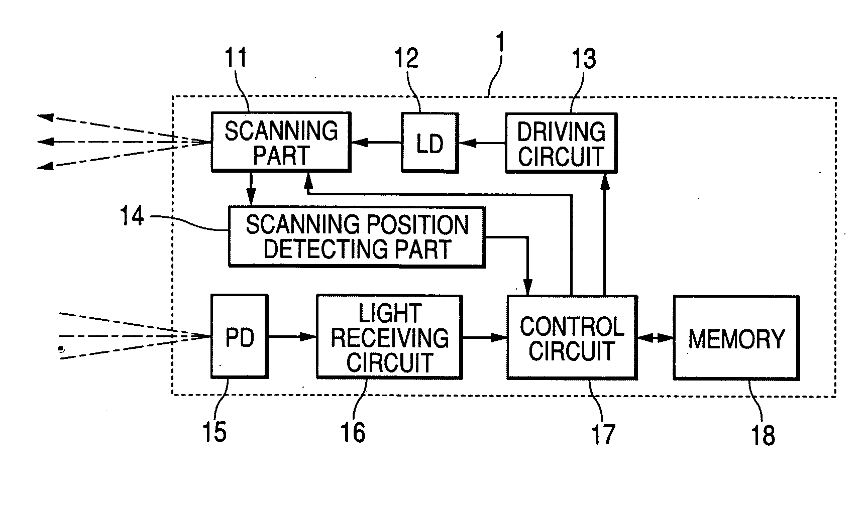
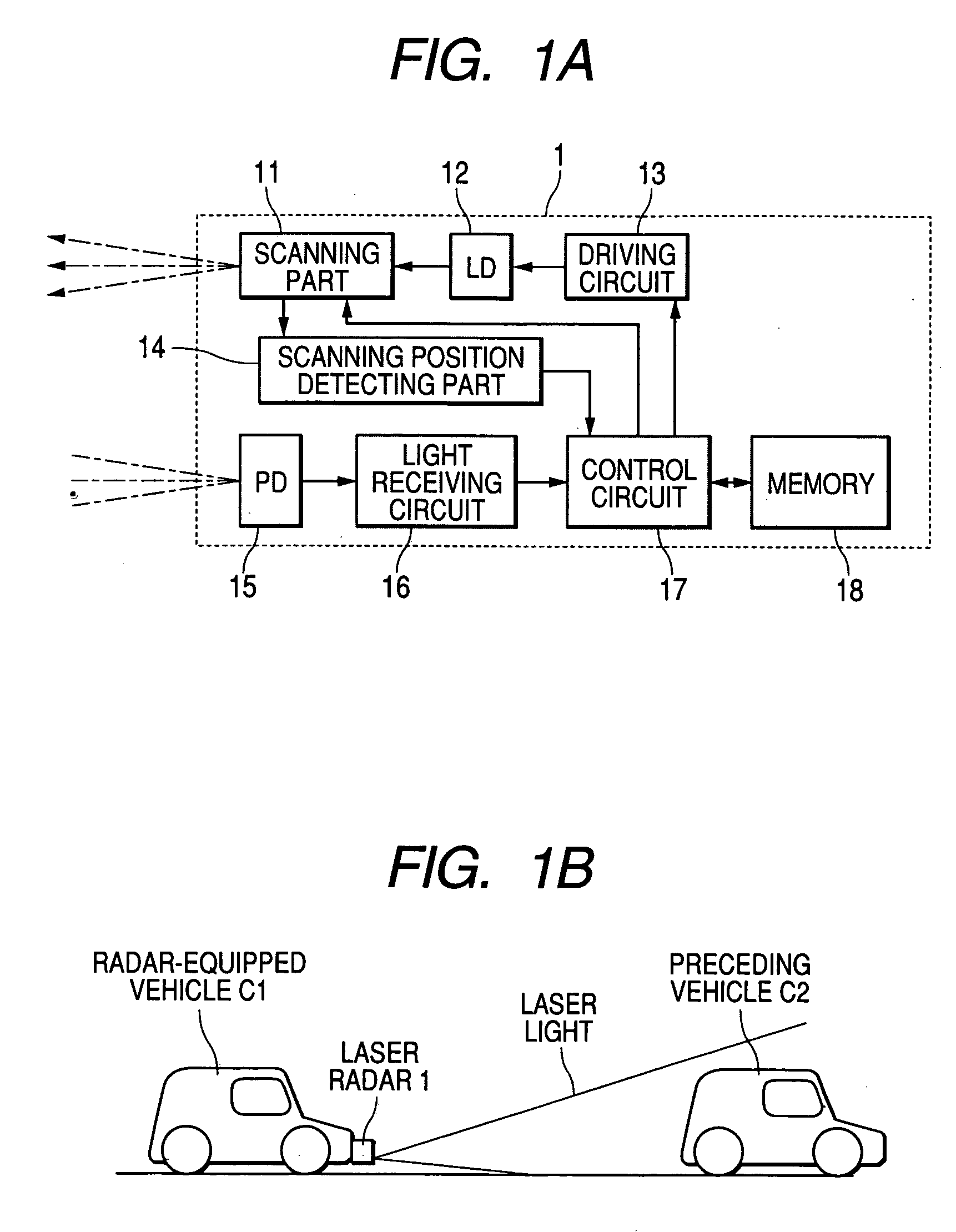
[0047]FIGS. 1A and 1B are views aiding in describing a vehicular radar device according to the preferred embodiment of the invention. FIG. 1A is a view showing the construction of the device, while FIG. 1B is a view showing an example in which the vehicular radar device is installed on a vehicle.

[0048] In FIG. 1A, the vehicular radar device (in this embodiment, a pulse-echo type of laser radar) is denoted by reference numeral 1. This vehicular radar device 1 has a scanning part 11, an LD (laser diode) 12, a driving circuit 13, a scanning position detecting part 14, a PD (photodiode) 15, a light receiving circuit 16, a control circuit 17, and a memory 18.

[0049] The control circuit 17 corresponds to control processing means in the invention. The scanning device 11, the LD 12 and the driving circuit 13 constitute transmitting means of the vehicular radar device 1, and t...


PUM


Abstract

A vehicular radar device capable of accurately detecting rain or the like or a road surface by discriminating between the rain or the like or the road surface and others. The vehicular radar device has a control circuit which performs a detection operation in an up state in which the visual field of the radar is shifted comparatively upwardly in the vertical direction so that the road surface is not detected, and determines that, from among detection data obtained during the up state, detection data which does not vary in reception intensity nor in reception delay time (distance data) for a predefined time is detection data relative to rain or the like, and which performs a detection operation in a down state in which the visual field of the radar is shifted comparatively downwardly in the vertical direction so that the road surface is positively detected, and determines that, from among detection data obtained during the down state, detection data which varies in reception delay time compared to a detection operation in an immediately previous normal state is detection data relative to the road surface.

Description

BACKGROUND OF THE INVENTION [0001] 1. Field of the invention [0002] The present invention relates to a vehicular radar device installed on, for example, a vehicle and operative to detect the presence or absence of a preceding vehicle or the like and position information on the same by using electromagnetic waves such as laser light. [0003] 2. Description of the Related Art [0004] Wide advances have heretofore made in the development of radars to be used in vehicles for purposes such as monitoring of forward obstacles and adaptive cruise control (vehicular radar devices), and a radio wave system and a laser system are known. Each of these systems is constructed to transmit an electromagnetic wave such as a radio wave or laser light toward an object within a predetermined detection area, and finds the distance to the target from a reception delay time which elapses until the radar receives a reflected wave of the electromagnetic wave. There is also another system which detects the dir...

Claims


Application Information

Patent Timeline
IPC IPC(8): G01S17/931G01S7/48G01S17/95
CPCG01S17/936G01S7/4802G01S17/931
Inventor ARITA, SATORUASADA, YASUTADA
Owner OMRON AUTOMOTIVE ELECTRONICS CO LTD
Why Eureka
Try Eureka