Display device

a display device and panel-type technology, applied in the direction of identification means, instruments, lighting and heating apparatus, etc., can solve the problems of lowering the assembly accuracy of the display element, and achieve the effect of preventing the lowering of the adhesive property and the floating of the display elemen

Active Publication Date: 2005-02-17
PANASONIC LIQUID CRYSTAL DISPLAY CO LTD
View PDF7 Cites 16 Cited by
  • Summary
  • Abstract
  • Description
  • Claims
  • Application Information

AI Technical Summary

Benefits of technology

[0018] Further, with respect to the display device which fixes the display element to the mold casing using a double coated tape, it is possible to prevent the lowering of the adhesive property attributed to the presence

Problems solved by technology

However, with respect to the display device which is configured such that in the mold casing which houses the light guide plate, the display element which adopts the glass substrate as a constitutional element thereof is housed, there exists the possibility that when the display element is housed

Method used


Image

  • Display device
  • Display device
  • Display device

Examples


embodiment 1

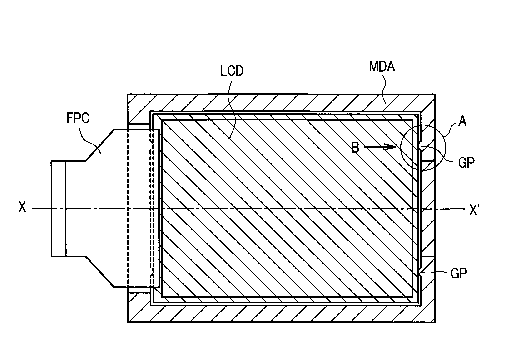
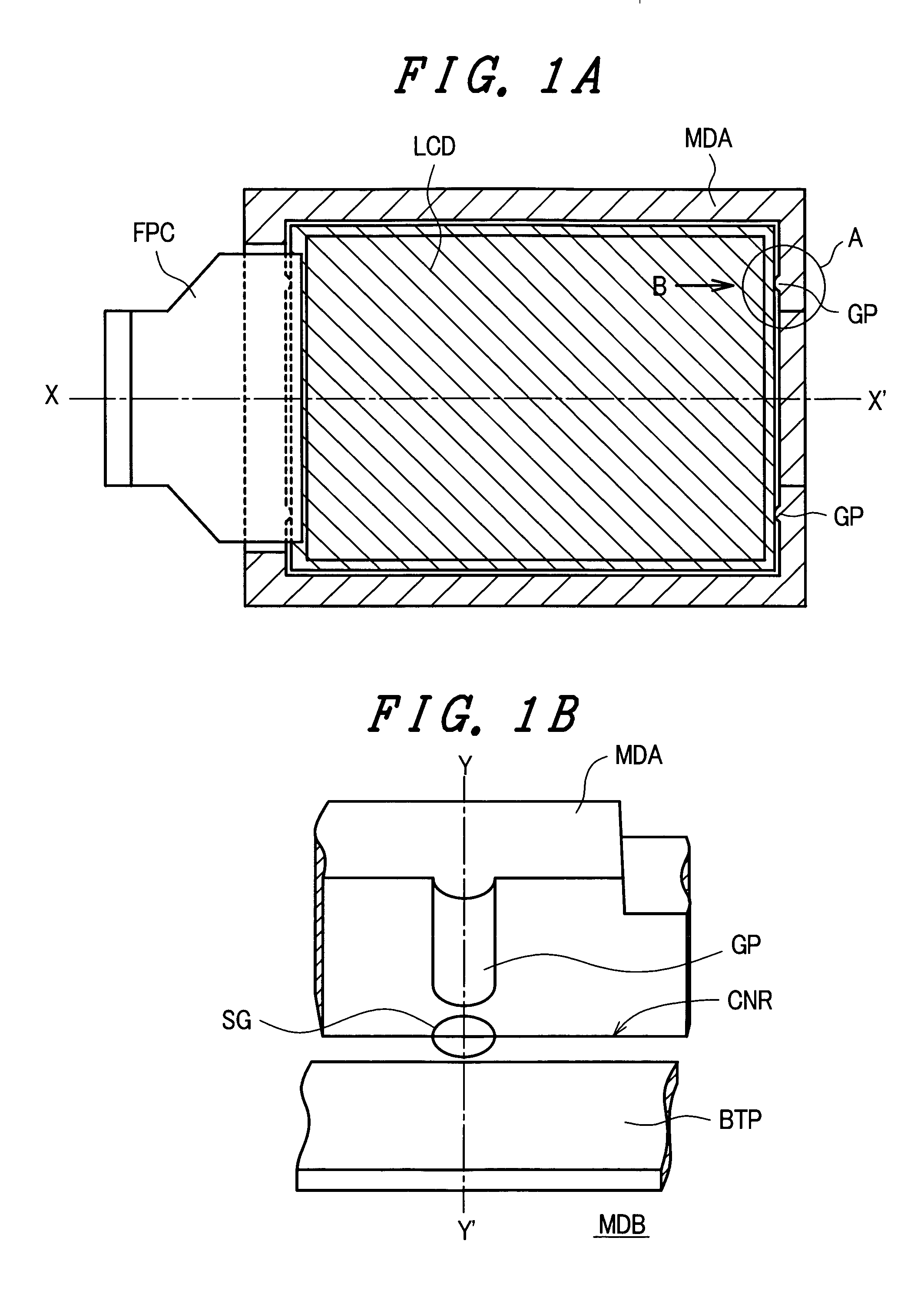
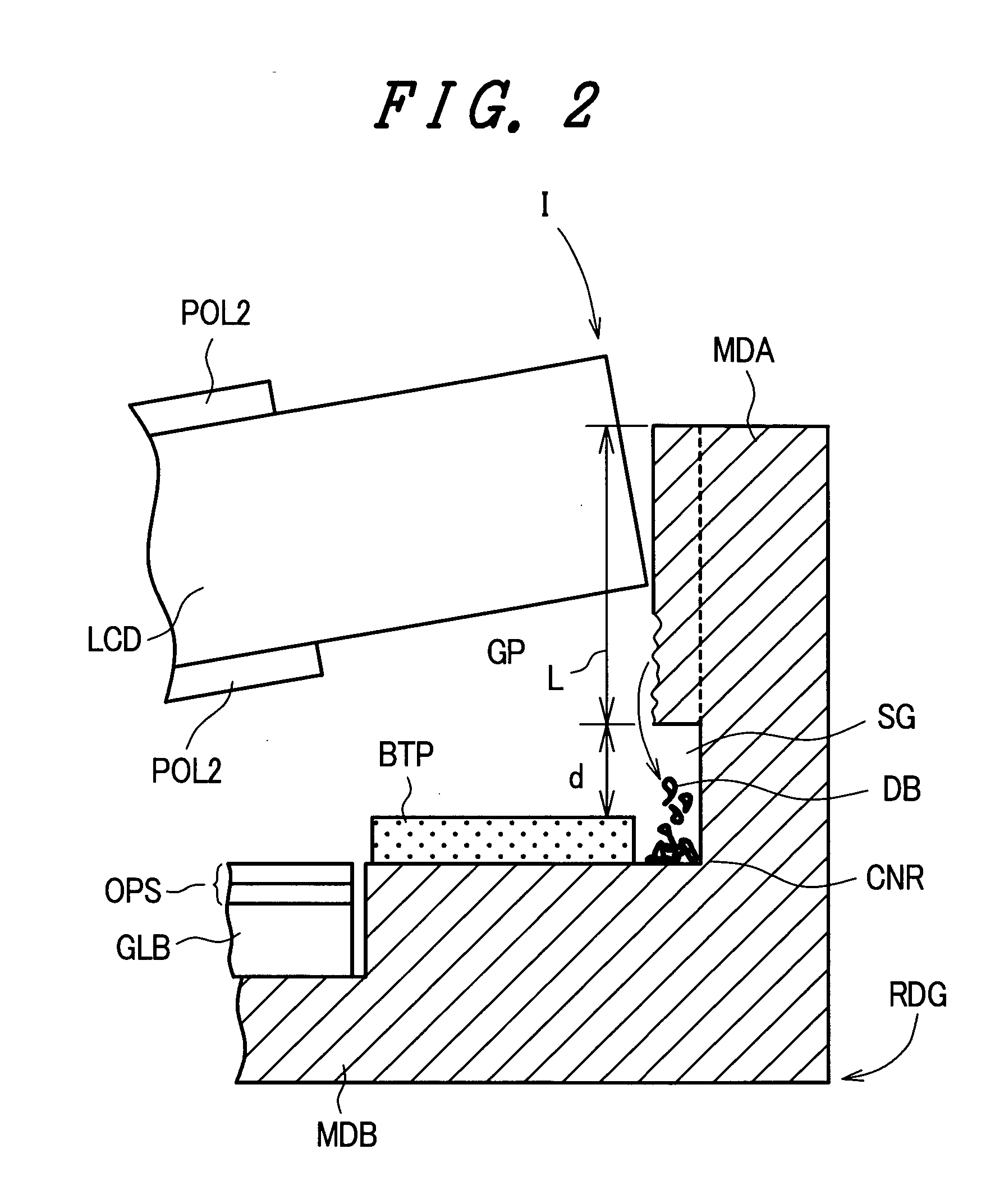
[0029]FIG. 1A and FIG. 1B are schematic views for explaining the constitution of a display device according to an embodiment 1, wherein FIG. 1A is a plan view of the display device and FIG. 1B is a perspective view of an essential part showing a portion A in FIG. 1A in the direction B from an oblique upper position. Further, FIG. 2 a cross-sectional view of an essential part taken along a line Y-Y′ in FIG. 1B.

[0030] The display device which is explained in conjunction with FIG. 1A, FIG. 1B and FIG. 2 is a liquid crystal display device using a liquid crystal display element as a display element. The liquid crystal display device is constituted by housing a light guide plate, an optical compensation sheet (a diffusion sheet, a prism sheet) OPS and the liquid crystal display element LCD in a casing which is a molded product made of a resin material (a mold casing) in a stacked manner. The mold casing is constituted of a picture-frame-like portion MDA which opens in a front surface side...

embodiment 2

[0041] In the same manner as the above-mentioned respective embodiments, the light guide plate GLB and the optical sheet OPS are housed in the recessed portion formed in the bottom portion MDB of the mold casing and the liquid crystal display element LCD is housed in the mold casing. On a stepped surface formed between the recessed portion of the bottom portion MDB of the mold casing and the picture-frame-like portion MDA, a double coated tape BTP is provided, and a periphery of a back surface of the inserted liquid crystal display element LCD is fixed to the bottom portion MDB of the mold casing. Other constitutions are substantially equal to the constitutions of the embodiment 1 and the

[0042] According to the constitution described in this embodiment, in housing the liquid crystal display element LCD in the mold casing, all of or most of the produced shaved-off debris DB is discharged to the outside of the mold casing through the opening HOL from the gap. Accordingly, no debris DB...

embodiment 4

[0043]FIG. 8 is a perspective view of an essential part of a display device according to an embodiment 4 similar to FIG. 1B. Further, FIG. 9 is a cross-sectional view taken along a line Y-Y′ in FIG. 8. In this embodiment, a pair of guide projections GP are formed respectively on inner walls of two sides of a picture-frame-like portion MDA of a mold casing which face each other in the line X-X′ direction in FIG. 1A.

[0044] The guide projections GP formed on the inner walls of the picture-frame-like portion MDA of the mold casing have an approximately semi-circular cross section and have the longitudinal direction thereof arranged parallel to the Y-Y′ direction. However, a cross-sectional shape of the guide projections GP is not limited to such a shape and may be versatile shapes as explained in conjunction with the above-mentioned respective embodiments. Further, the guide projections GP are not always formed on the above-mentioned inner walls of two opposing sides and may be formed o...


PUM


Abstract

The present invention prevents a defective display attributed to a non-uniform gap between a display element and a backlight which is caused by a phenomenon that an inner wall of a mold casing is shaved off by an end periphery of the display element and a shaved-off debris remains between the casing and the display element. Guide projections are integrally formed on an inner wall of a picture-frame-like portion of the mold casing and, at the same time, a gap which accommodates the shaved-off debris is formed between the guide projection and a bottom portion of the mold casing.

Description

BACKGROUND OF THE INVENTION [0001] 1. Field of the Invention [0002] The present invention relates to a panel-type display device, and more particularly, the present invention is preferably applicable to a display device in which a frame-like casing which is made of a material softer than a material of substrates which constitute a display element is provided and the display element is integrally housed and held in the casing, for example, a miniaturized display element having the small assembling tolerance of a display element and a casing such as a liquid crystal display device mounted on a mobile phone or the like or an organic light emitting display device. [0003] 2. Description of the Related Art [0004] With respect to the assembling of plate-like members which constitute a panel-type display device and a casing which houses the plate-like members, there has been known a panel-type display device which is disclosed in Japanese Patent Laid-open Hei7 (1995)-261173 (literature 1). ...

Claims


Application Information

Patent Timeline
IPC IPC(8): G02F1/13G02F1/13357G02F1/1333G09F9/00
CPCG02F1/133308G02F2001/133325G02F2001/133322G02F1/133615G02F1/133325G02F1/133322
Inventor OHTOMO, ATSUSHIKATOU, MASAHIRO
Owner PANASONIC LIQUID CRYSTAL DISPLAY CO LTD
Why Eureka
Try Eureka