
High durability touch screen and method for manufacturing

a touch screen and high durability technology, applied in the direction of static indicating devices, instruments, synthetic resin layered products, etc., can solve the problems of high cost and challenge in laminating the pet substrate to the ultrathin glass substrate, and achieve the effect of durable touch screen

Active Publication Date: 2005-02-17
TRENDON TOUCH TECHNOLOGY CORPORATION
View PDF21 Cites 39 Cited by
  • Summary
  • Abstract
  • Description
  • Claims
  • Application Information

AI Technical Summary

Benefits of technology

[0006] The present invention provides a method to achieve a durable touch screen without the need for lamination of the PET film or substrate to the ultrathin glass substrate for the top sheet of, for example, a resistive touch screen product configuration.
[0007] According to an aspect of the present invention, a method of manufacturing a high durability touch screen comprises deposition of a transparent conductive thin film directly on an ultrathin glass substrate, preferably using vacuum based physical vapor deposition such as sputtering. The ultrathin glass substrate may be coated with one or more transparent conductive or semi-conductive films, and may be used, for example, as the top sheet in a display or touch screen device. Furthermore, the method of the present invention may render economically the addition of other functional coatings associated with top sheets for display devices, such as anti-glare coatings or diffuser surface coatings and / or anti-reflective coatings, and / or anti-abrasion coatings or the like. Aspects of the present invention may be equally suitable for use in manufacturing resistive touch screen devices and capacitive touch screen devices.

Problems solved by technology

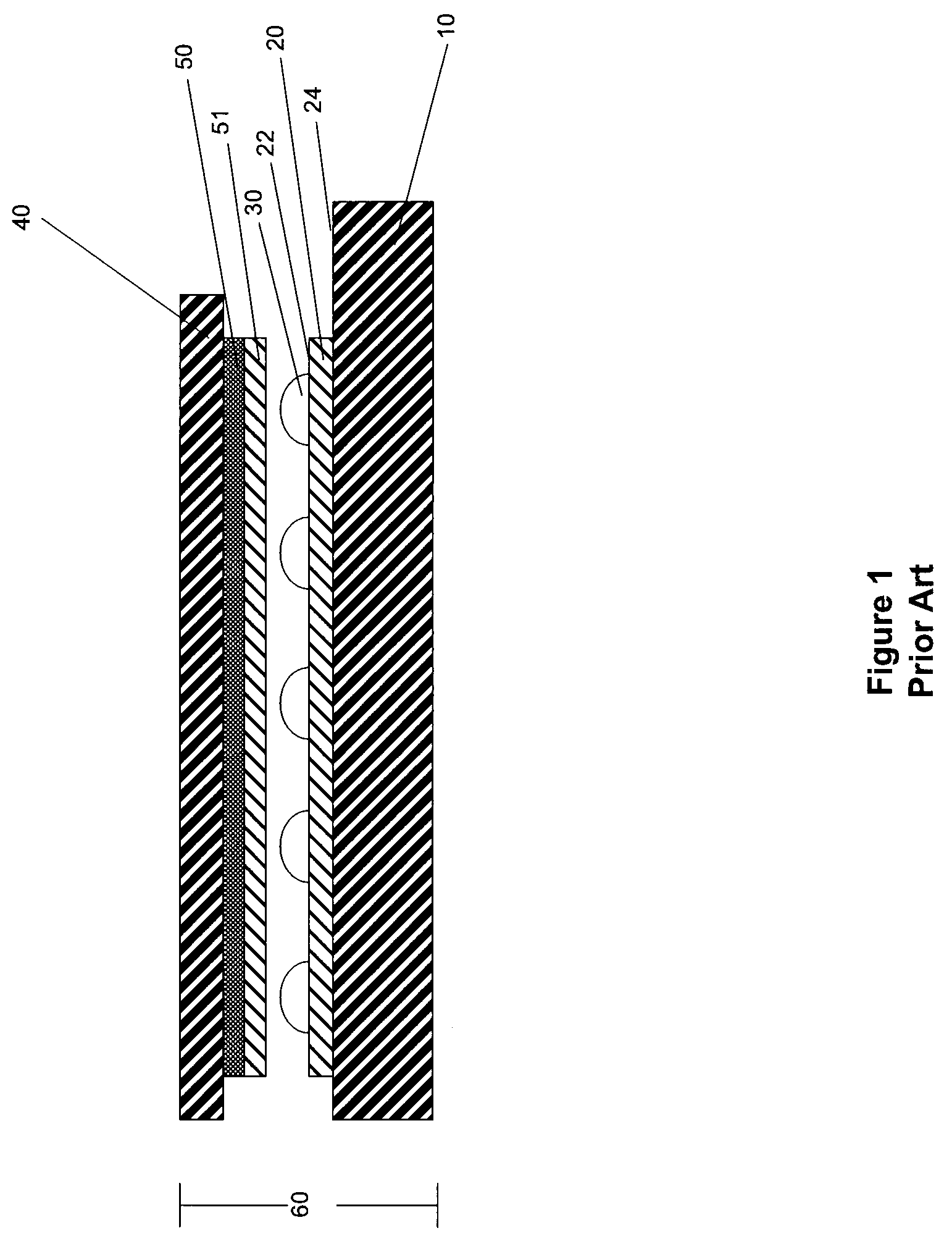
Although the above configuration can work well in certain circumstances, steps involved in laminating the PET substrate to the ultrathin glass substrate can be challenging and costly.

Method used


Image

  • High durability touch screen and method for manufacturing
  • High durability touch screen and method for manufacturing
  • High durability touch screen and method for manufacturing

Examples


Embodiment Construction

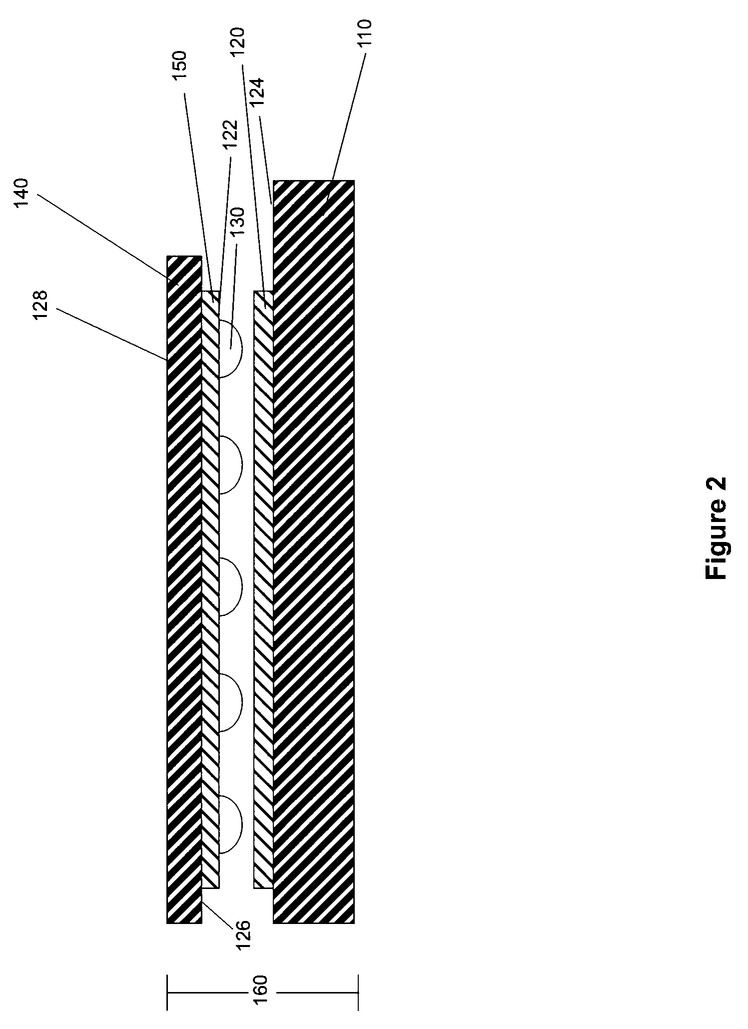
[0020] Referring now to the drawings and the illustrative embodiments depicted therein, a resistive touch screen 160 in accordance with the present invention is shown in FIG. 2. Resistive touch screen 160 includes a transparent rigid substrate 110, which can be glass, polymeric, acrylic, plastic or the like, most preferred a transparent plastic cyclic olefin copolymer (such as described in U.S. patent application Ser. No. 09 / 946,228, filed Sep. 5, 2001 by Ippel et al. for IMPROVED PLASTIC SUBSTRATE FOR INFORMATION DEVICES AND METHOD FOR MAKING SAME (Attorney Docket DON03 P-910), which is hereby incorporated herein by reference), with a transparent conductive or semi-conductive thin film 120 (such as indium tin oxide (ITO) or the like in the sheet resistance range of about 150 to about 900 ohms per square, most preferably in the range of about 400 to about 600 ohms per square, with a physical thickness of about 500 angstroms or less) deposited thereon, such as by sputtering onto a su...


PUM

PropertyMeasurementUnit
Lengthaaaaaaaaaa
Electrical conductoraaaaaaaaaa
Durabilityaaaaaaaaaa

Abstract

A method for manufacturing a touch screen that deposits a conductive layer or coating directly onto a surface of a sheet or ribbon or roll of thin glass material. The coated thin glass material may be cut to the desired shape or substrate for use as the outer, thin glass substrate of the touch screen device. Spacer elements and / or other functional coatings or layers or the like may also be applied to the conductive layer or opposite surface of the thin glass ribbon. Optionally, a functional coating or layer may be deposited or applied to a surface of a pre-cut thin glass substrate. The coated pre-cut thin glass substrate may be used as a top sheet for lamination as the protective top sheet of a touch screen device.

Description

CROSS REFERENCE TO RELATED APPLICATIONS [0001] The present application claims benefit of U.S. provisional application, Ser. No. 60 / 484,713, filed Jul. 3, 2003 (Attorney Docket DON03 P-1105), which is hereby incorporated herein by reference in its entirety.FIELD OF INVENTION [0002] The present invention relates generally to touch screens and methods for manufacturing touch screens. BACKGROUND OF INVENTION [0003] As the use of touch screens, such as for public information kiosks, portable devices, and gaming applications and the like, increases, so does the need for more durable touch screen designs. Use of lamination configurations is a known technique to enhance durability of and add features (such as conductive, anti-glare, and anti-reflective coatings) to the touch screens. For example, using a transparent, conductively coated flexible plastic material, such as transparent conductively coated PET laminated to ultrathin glass (having a glass thickness preferably less than about 0.3...

Claims


Application Information

Patent Timeline
IPC IPC(8): B32B3/00B32B17/10B32B27/32B32B38/16C03C17/34C03C27/06G06F3/033G06F3/044G06F3/045G09G5/00
CPCB32B17/10018Y10T29/49128B32B27/32B32B38/162B32B2037/246C03C17/3417C03C27/06G06F3/044G06F3/045Y10T29/49126Y10T29/4913Y10T29/49155Y10T428/24926Y10T29/49117Y10T428/24917B32B17/10174G06F3/0445
Inventor HALSEY, EUGENE IVGETZ, CATHERINE A.
Owner TRENDON TOUCH TECHNOLOGY CORPORATION
Learn More