Methods and apparatus for minimally invasive transverse aortic banding

a transverse aortic and vesicle technology, applied in the field of biotechnology, can solve the problems of difficult tying of knots intracorporeally, requiring significant experience and/or time, and limited operation space, so as to facilitate ligation or constriction of vesicle membranes, prevent or reduce tissue abrasion, and facilitate the effect of tying or constricting vesicle membranes

Inactive Publication Date: 2005-02-17
UNIV OF UTAH RES FOUND
View PDF13 Cites 3 Cited by
  • Summary
  • Abstract
  • Description
  • Claims
  • Application Information

AI Technical Summary

Benefits of technology

[0015] The invention further provides a tubular member that may be covered by a soft flexible material or sheath, such as a plastic, rubber, Teflon® and other like materials which prevent or reduce abrasion of tissues within a subject. The invention further provides a soft flexible material that is slidably engaged to at least the tubular member.
[0016] The invention also provides a method for a minimally invasive ligation procedure, facilitating ligation or constriction of a vesicular membrane. When used in combination with a suture manipulation device such as a pair of forceps, the curved suture applicator is used to easily dispose a silk or nylon suture around a mammalian vesicle. Where appropriate, a predetermined constriction may be achieved by placing a spacing apparatus substantially parallel to the target vesicle. The suture is then tied, creating either a ligation or a constricting band

Problems solved by technology

In certain surgeries, particularly in small animals, operational space may be very limited.
Second, threading a suture around an object can require significant experience and/or be very time consuming.
Again, if space is limited, tying the knot intracorporeally can be very challenging.
However, using this technique may require a more expensive apparatus for performing the ligation.
Additionally, because foreign matter such as a clip may be left in the body, the range of application of this technique is limited.
However, many such devices do not allow the operator to pass a thread or suture

Method used


Image

  • Methods and apparatus for minimally invasive transverse aortic banding
  • Methods and apparatus for minimally invasive transverse aortic banding
  • Methods and apparatus for minimally invasive transverse aortic banding

Examples


example i

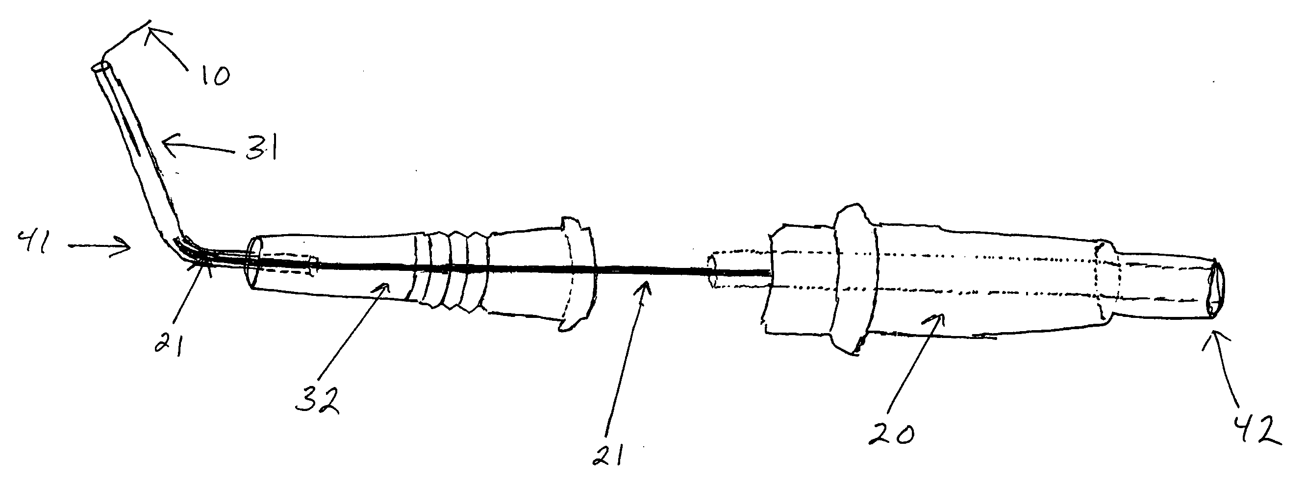
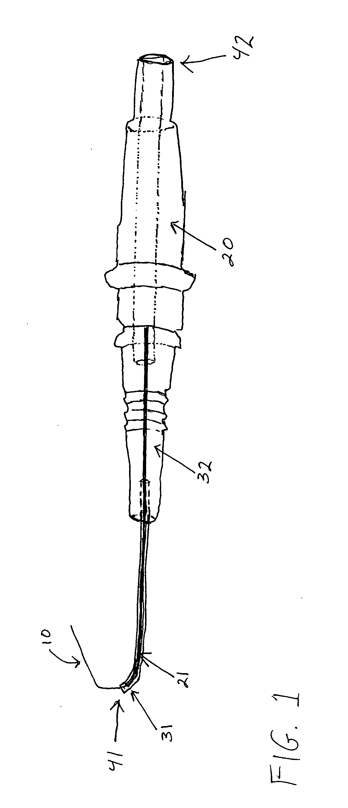
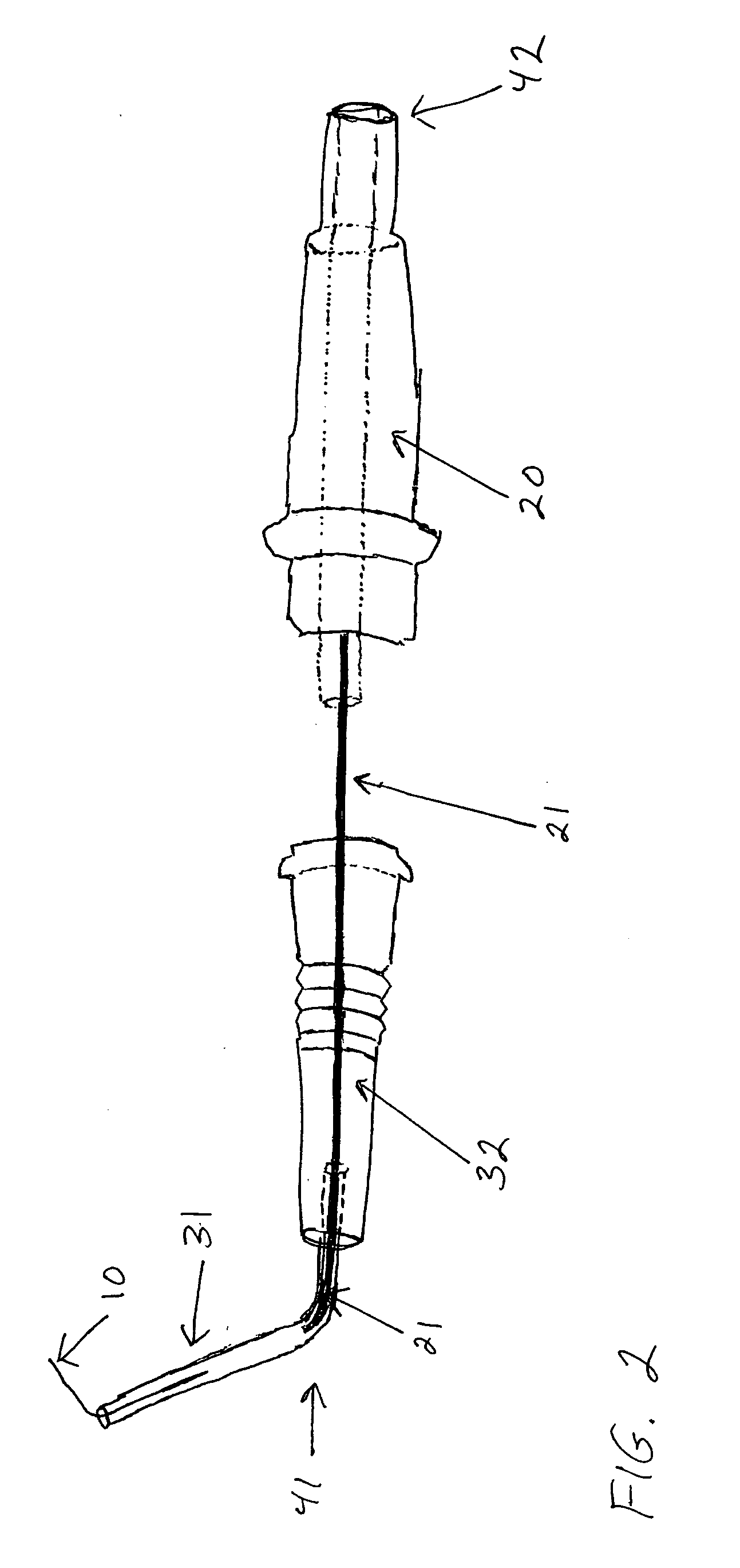
[0043] To further illustrate the present invention, consider once again the use of the curved suture applicator in the aforementioned MTAB technique. FIG. 1 is a photograph of latex casts of aortas following MTAB (left) and sham surgery (right). The silk ligature has been removed from the aorta, but the site of narrowing is evident (arrow demonstrates location of constriction). Aortic constriction, as shown in FIG. 1, and as performed by applying the present invention, may be used to artificially simulate hypertension, thus initiating a chain of events in the left ventricle of the heart in response to the higher blood pressure. Over a sufficient time period, the left ventricle of the affected heart will begin to enlarge. It is this resulting left ventricle hypertrophy that often leads to congenital heart failure. Thus, by using the present invention to simulate left ventricular hypertrophy, other studies and experiments may be conducted on the hypertrophied heart to determine the na...


PUM


Abstract

A curved suture applicator is provided for facilitation of ligation procedures in mammals. The said curved suture applicator enables a surgeon to efficiently encircle a target tissue such as a blood vessel with a suture or thread. A kit is also provided, comprising the said curved suture applicator, an appropriate length of suture or thread, and a suture manipulation device, such as a pair of forceps. Furthermore, a minimally invasive ligation method is provided that utilizes the said curved suture applicator and kit to efficiently band the transverse aorta of small mammals. Such banding is useful in studying and simulating the effects of left ventricular hypertrophy as it relates to congenital heart failure.

Description

CROSS REFERENCE TO RELATED APPLICATION [0001] This application claims the benefit under 35 U.S.C. § 119(e) of U.S. Provisional Application No. 60 / 475,677, filed Jun. 3, 2003, which is incorporated herein by reference.GOVERNMENT RIGHTS [0002] The United States government may have rights in the invention pursuant to grants from the Department of Veterans Affairs and the National Institute of Health (HL 52338-06, U01-70525, T32HL7576, HL5807).TECHNICAL FIELD [0003] The present invention relates generally to biotechnology, more specifically, to ligation surgical techniques and a surgical apparatus. The present invention relates to minimally invasive methods and apparatus for vesicle constriction. BACKGROUND [0004] Procedures for ligating tissues in surgical operations are frequently performed. Generally, ligation may take the form of a constricting band composed of a thread or suture. The thread or suture is passed around the target vessel and then tied into a constricting band. The kno...

Claims


Application Information

Patent Timeline
IPC IPC(8): A61B17/00A61B17/06A61B17/12A61B19/00
CPCA61B17/0483A61B17/12013A61B2017/00349A61B2019/481A61B2017/0608A61B2017/061A61B2017/0046A61B2090/08021
Inventor HU, PINGZHANG, DONGFANGSWENSON, LEANNELITWIN, SHELDON E.
Owner UNIV OF UTAH RES FOUND
Why Eureka
Try Eureka