Occlusive coil manufacture and delivery

a coil and occlusion technology, applied in the field of occlusion coil manufacture and delivery, can solve the problems of affecting the operation of the tubular organ, etc., and achieve the effect of restricting the movement of the wir

Inactive Publication Date: 2005-02-17
JAYARAMAN SWAMINATHAN
View PDF53 Cites 185 Cited by
  • Summary
  • Abstract
  • Description
  • Claims
  • Application Information

AI Technical Summary

Benefits of technology

[0029] The present invention further relates to a method of manufacturing a superelastic device for placement inside an anatomical defect, including: providing an inner mandril of a preselected shape for supporting a coil of a wire formed of a shape memory material; winding the wire about the mandril to create a coil conforming to the mandril shape; providing an outer mold to completely surround the coil and mandril and thereby constrain movement of the wire with respect to the mandril; heating the outer mold for a predetermined period of time while the outer mold surrounds the coil and mandril; and allowing the coil to cool.

Problems solved by technology

In various body tissues, defects may occur either congenitally or as a result of operative procedures.
Such defects may include abnormal openings, for example, in the cardiovascular system including the heart.
Such as hole in the septum often requires an invasive procedure for closure of the defect.
For example, the geometry of the lumen in instances of PDA often requires complicated positioning of the coil for proper functioning.
These materials are inappropriate for the present development because they do not have the shape memory properties of materials such as nitinol.
Failure to implant occurred in 5% of the cases.
Analysis of data from the coil registry has revealed that an acute occlusion rate and failure was significantly related to coil size.
While the registry does not address the overall success rate of closure of PDA-associated ducts greater than 4 mm in size because of the statistical limitations of the data set, the immediate results of procedures directed to large ducts are encouraging.
It should be noted, however, that left artery stenosis and failure of the procedure were associated with attempts on neonates and infants.
Thus, the effectiveness of coils appears to be unquestionably demonstrated.

Method used


Image

  • Occlusive coil manufacture and delivery
  • Occlusive coil manufacture and delivery
  • Occlusive coil manufacture and delivery

Examples


Embodiment Construction

[0061] In the description which follows, any reference to either direction or orientation is intended primarily and solely for purposes of illustration and is not intended in any way as a limitation to the scope of the present invention. Also, the particular embodiments described herein, although being preferred, are not to be considered as limiting of the present invention.

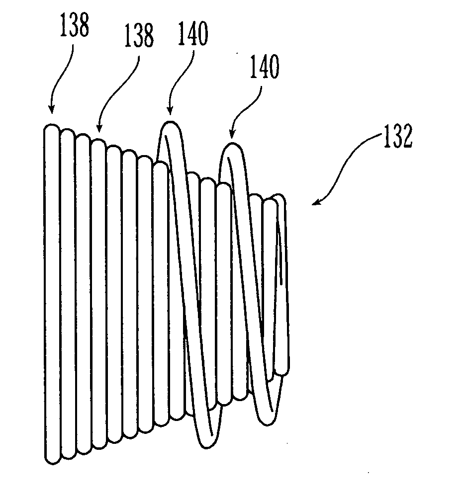
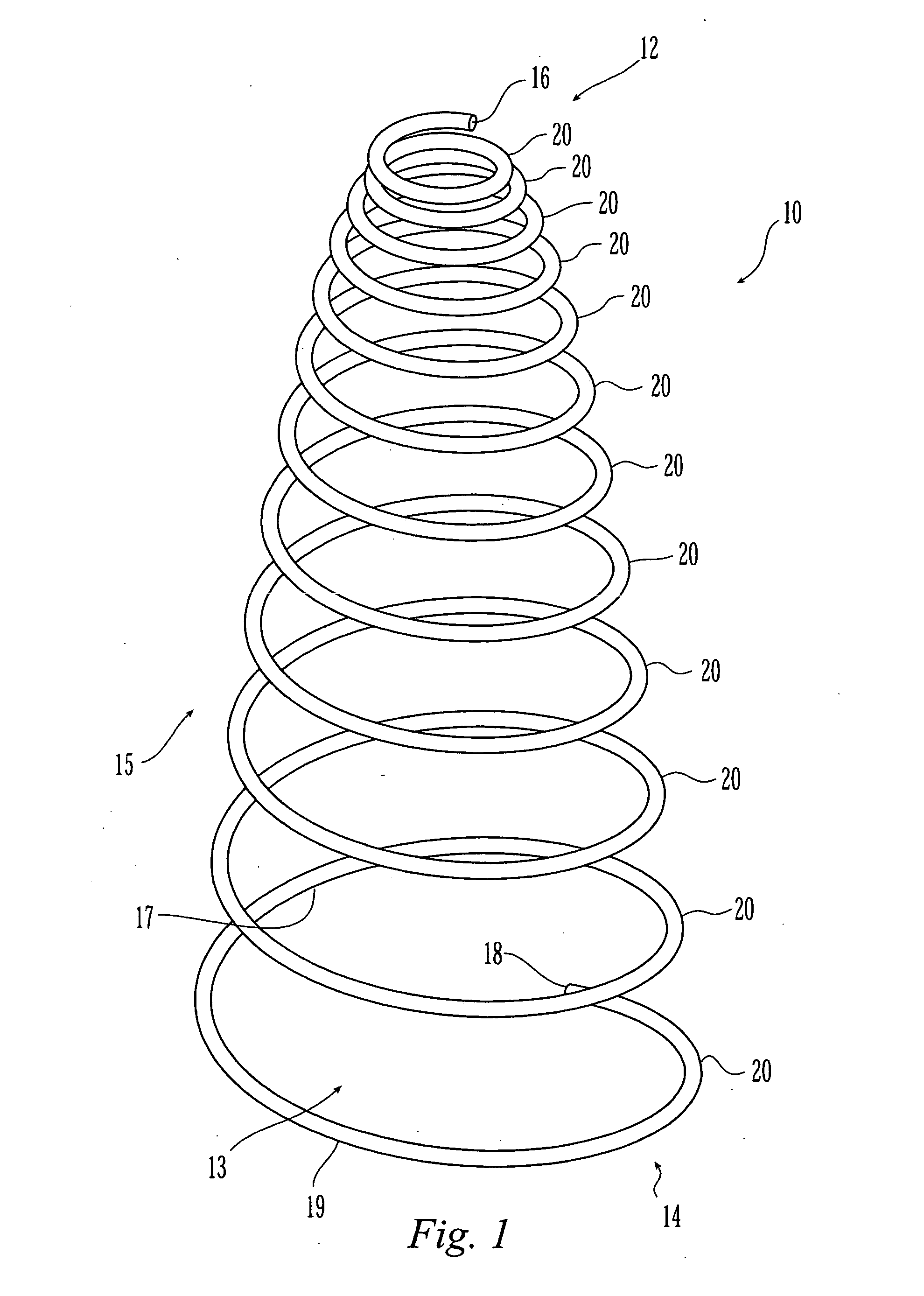
[0062] The most preferred applications of the shape memory alloy members of the present invention are as vasoocclusive devices for filling or blocking anatomical defects, such as openings, in the vascular tree, e.g., holes in veins, arteries or the heart of a mammal. The coil portion of the device is placed or allowed to extend within the opening, where it is contacted by blood. Blood thrombosis upon contact with the coil thus fills in open areas to prevent further blood transport through the defect.

[0063] Referring to FIG. 1, there is shown a device or coil 10 that is formed in a conical spring configuration w...


PUM


Abstract

The present invention includes a coiled wire formed of a shape memory material for implantation into an anatomical defect. After implantation of one or more of the coiled wires according to the present invention, the defect is occluded and thereby corrected or treated. Prior to implantation, the coiled wire is generally elongated and thereafter it reverts to a predetermined shape that is suitable for occluding the defect. At least one clip having at least two prongs may be provided on the wire for attachment to body tissue. Preferably the wire is made of nickel-titanium. In an alternative embodiment, the coil includes a plurality of layers. At least one of these layers is formed of a shape memory material.

Description

CROSS-REFERENCE TO RELATED APPLICATIONS [0001] This application is a Divisional of U.S. patent application Ser. No. 09 / 739,830, filed Dec. 20, 2000, which claims priority of Provisional Application Ser. No. 60 / 171,593 filed Dec. 23, 1999 under 35 U.S.C. § 119(e).FIELD OF THE INVENTION [0002] The present invention relates to a device for filling an anatomical defect. In particular, the device of the present invention is formed of a member which includes a shape memory alloy. BACKGROUND OF THE INVENTION [0003] In various body tissues, defects may occur either congenitally or as a result of operative procedures. Such defects may include abnormal openings, for example, in the cardiovascular system including the heart. Procedures have been developed to introduce devices for closing such abnormal openings. Embolization, the therapeutic introduction of a substance into a vessel in order to occlude it, is a treatment used in cases such as patent ductus arteriosus (PDA), major aortopulmonary...

Claims


Application Information

Patent Timeline
Patent Type & Authority Applications(United States)
IPC IPC(8): A61B17/00A61B17/12
CPCA61B17/0057A61B2017/12095A61B17/12109A61B17/12113A61B17/1214A61B17/12145A61B17/1215A61B17/12172A61B17/12177A61B2017/00575A61B2017/00592A61B2017/00606A61B2017/00623A61B2017/00867A61B17/12022
Inventor JAYARAMAN, SWAMINATHAN
Owner JAYARAMAN SWAMINATHAN
Why Eureka
Try Eureka