
Method for analyzing performance information

a performance information and performance analysis technology, applied in the field of system for displaying/analyzing performance information, can solve the problems of volume assignment and storage performance management, storage device becomes a bottleneck for the whole system, serious performance degradation in some cases, etc., and achieves the effect of facilitating the discrimination of a server group and bottleneck in performan

Inactive Publication Date: 2005-02-17
HITACHI LTD
View PDF25 Cites 26 Cited by
  • Summary
  • Abstract
  • Description
  • Claims
  • Application Information

AI Technical Summary

Benefits of technology

The present invention provides a method for identifying a server group that causes performance issues on a storage device. This is done by using a performance management tool that collects mapping information between the storage device and the servers and their performance information. The tool allows users to select a specific resource in the storage device and display the performance data of the server group that uses that resource. This helps to quickly identify the root cause of performance issues and take appropriate action to address them.

Problems solved by technology

On the other hand, however, since a plurality of servers share a single storage device, volume assignment and storage performance management become complicated.
Often, therefore, the storage device becomes a bottleneck for the whole system.
In a configuration in which a plurality of servers share and use a single storage device, I / O transactions from a plurality of servers overlap on a specific resource within the storage device and consequently serious performance degradation is caused in some cases.
As an example, I / O loads from a plurality of servers concentrate on a specific physical disk group within a storage device, and the I / O performance seen from the server side is not sufficiently exhibited due to the I / O contention.
In this method, however, it is difficult to discriminate the cause of an I / O contention performance problem caused by setting on the outside of the storage device, i.e., specifically a server group that burdens an I / O load on a specific resource within the storage device or a portion that becomes a bottleneck of the performance.

Method used


Image

  • Method for analyzing performance information
  • Method for analyzing performance information
  • Method for analyzing performance information

Examples


Embodiment Construction

[0030] Hereafter, an embodiment of the present invention in a SAN system in which a plurality of servers share a storage device will be described.

[0031] Examples of the SAN system in the embodiment described hereafter are simplified as compared with the ordinary SAN system because functions and details that are not necessary for description of the present embodiment are omitted. However, the application range of the present embodiment is not limited thereby.

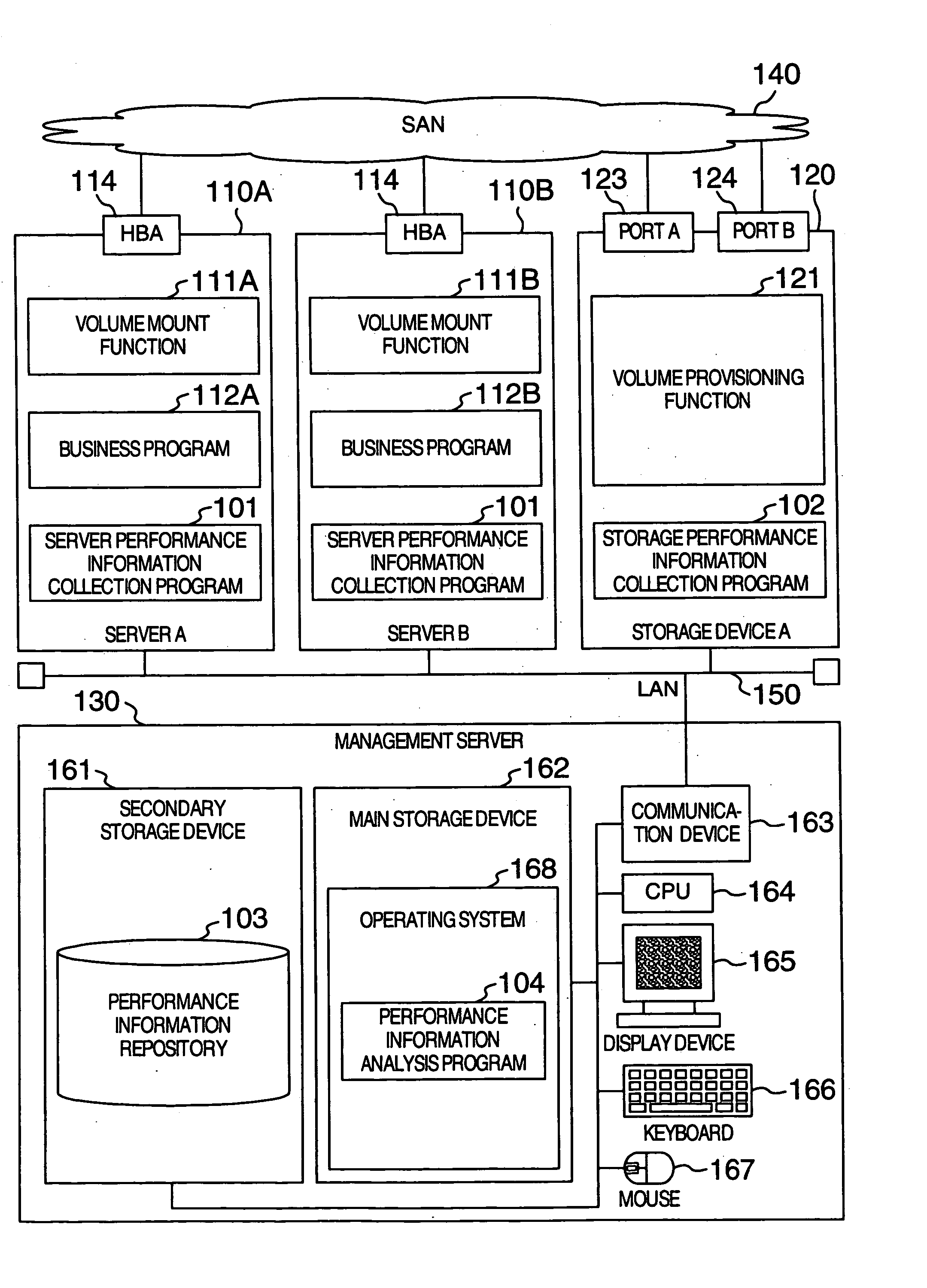
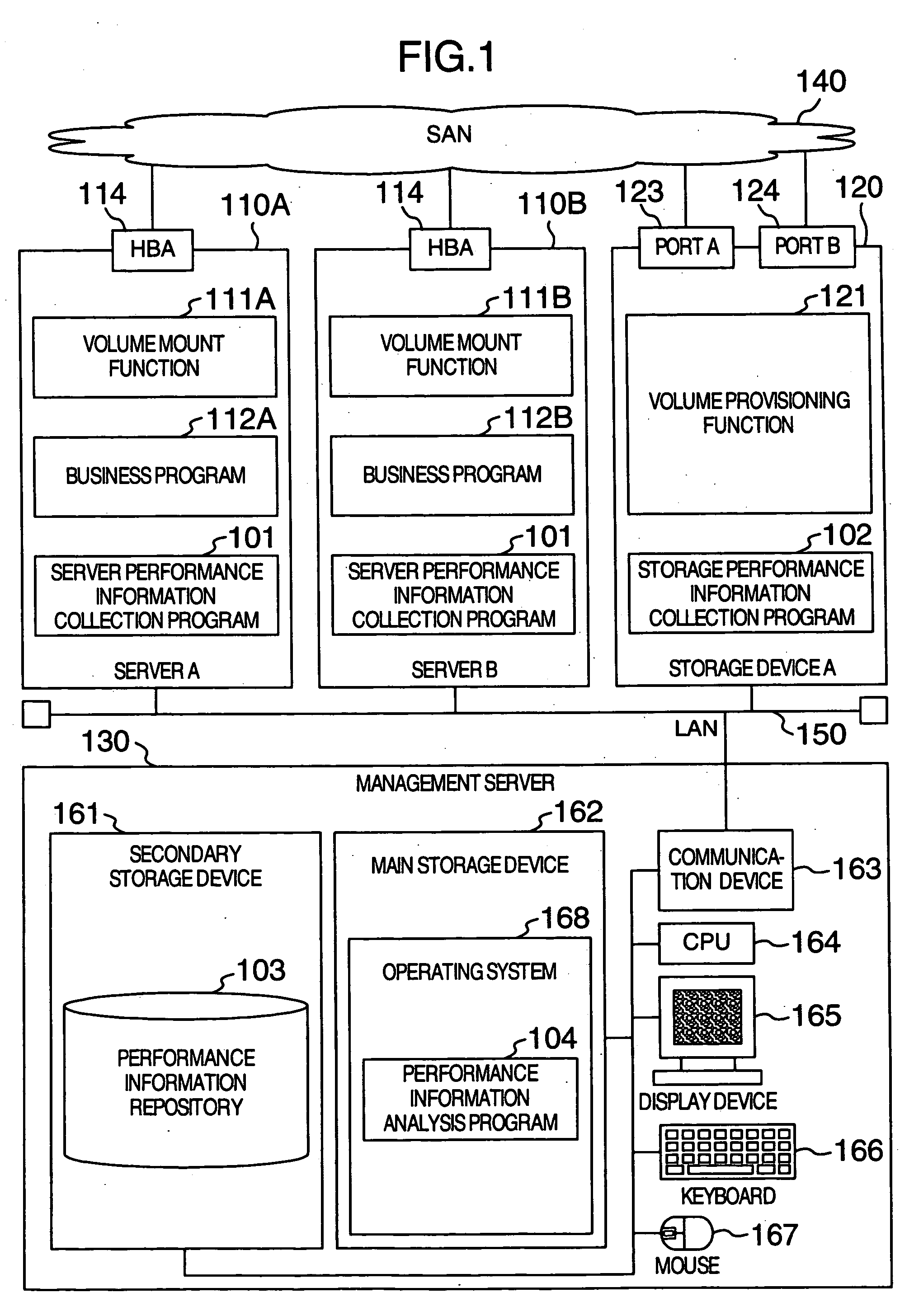
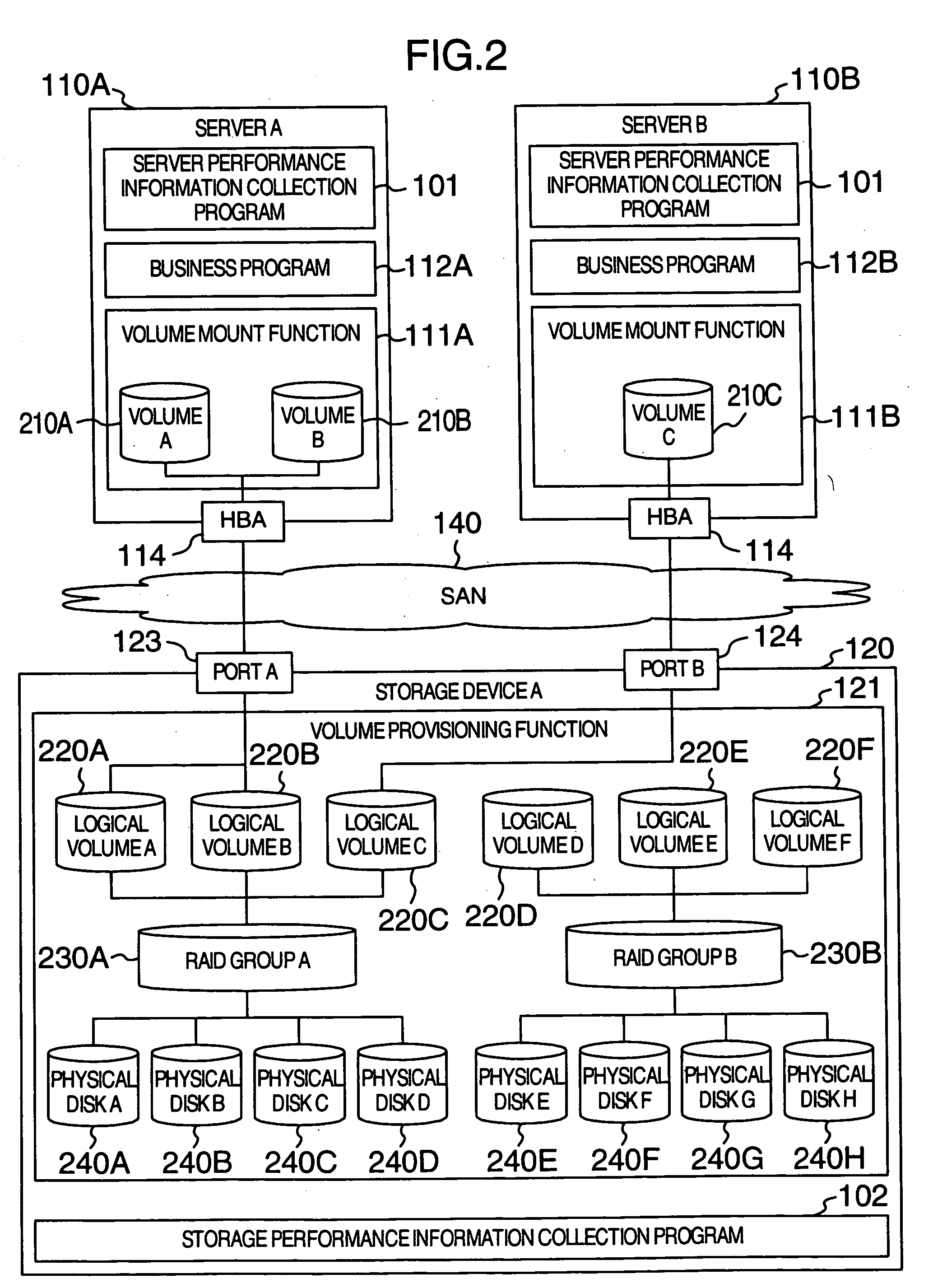
[0032]FIG. 1 is a diagram showing a configuration of a SAN system in the present embodiment. The present SAN system includes a storage device A 120, a server group including a server A 110A and a server B 110B, a SAN 140 for connecting the server group and the storage device to each other, a management server 130, and a LAN 150 for connecting the server group and the storage device to the management server 130. Each of the servers may be a computer in which a program is executed, a terminal device using the function of the comp...


PUM


Abstract

A performance information display method using a computer, includes the steps, in the computer, of reading out information data of a storage device previously stored in a storage device and information data of a plurality of devices utilizing the storage device, displaying an identifier of the storage device and identifiers of a plurality of devices utilizing the storage device on a screen on the basis of the information data read out, accepting a command to select the displayed identifier of the storage device, and displaying performance information data of the devices utilizing the selected storage device in association on the basis of the accepted command and the information data read out.

Description

BACKGROUND OF THE INVENTION [0001] The present invention relates to a system for displaying / analyzing performance information of servers and storage devices. [0002] In recent years, configurations in which a plurality of servers share a single storage device have increased because of the development of the SAN (Storage Area Network) technique. The reason why such configurations are increasing is that the localization of the operational business such as backup and fault control is facilitated and the operation management cost can be compressed. [0003] On the other hand, however, since a plurality of servers share a single storage device, volume assignment and storage performance management become complicated. A method for simplifying the volume assignment in the SAN environment is disclosed in US 2003 / 0005119A1. [0004] In computer systems, the storage device is a low speed storage medium as compared with caches and memories in the CPU. Often, therefore, the storage device becomes a b...

Claims


Application Information

Patent Timeline
Patent Type & Authority Applications(United States)
IPC IPC(8): G06F3/06G06F13/10G06F11/32G06F11/34G06F12/00G06F12/16H02H3/05
CPCG06F3/0605G06F3/061G06F3/0653G06F3/067G06F11/324G06F11/328G06F2201/885G06F11/3476G06F11/3485G06F11/3495G06F2201/80G06F2201/815G06F2201/87G06F11/3409G06F11/3433
Inventor TAKEDA, KEIKUSAMA, TAKATO
Owner HITACHI LTD
Learn More