
Production system

a production system and production system technology, applied in the direction of measuring/indicating equipment, other manufacturing equipment/tools, manufacturing tools, etc., can solve the problems of reducing the effort of such works, and carrying out mechanically with a comparatively high manual effort,

Inactive Publication Date: 2005-02-24
GROB WERKE BURKHART GROB E K
View PDF6 Cites 8 Cited by
  • Summary
  • Abstract
  • Description
  • Claims
  • Application Information

AI Technical Summary

Benefits of technology

Because of the design of the production system with a module-like construction of the single system components, respectively system modules, it is now possible to conceive suitable modules for very different tasks for the production system and to combine them with each other, respectively among each other, in any sequence and in any number. Therefore it is, for example, possible to construct a conveying line module-like which then, depending on the requirement of each plan, respectively customer wish, can be arranged in suitable length with the branching units necessary for it along a machining line with machine tools, respectively stations. The individual modules here are designed in such a way that they can be even transported easily. The module-like construction in particular is the reason why the modules do not have to be dismantled, respectively have to be dismantled only slightly, for transport. This reduces the effort for such works considerably as these are, in particular, essentially also operations which have to be carried out mechanically with a comparatively high manual effort. If the conception of the production system with a module-like construction is carried out consequently, besides the modular construction of the conveying lines, even such a construction is possible for the individual machining stations, which are then, for example, designed as process module also in the manner described above, in order to combine a combination with the conveying lines, respectively modules, and other system modules, like, for example, very different machining stations.
In summary it is stated that the central energy and media recycling, for example in the supplying module, has, among others, the following advantages: A number of small aggregates is avoided in, respectively on, the process modules. This results in a reducing of costs, simpler maintenance, for example by an oil change which is only required on a central unit, respectively a central aggregate, a higher availability by a smaller complexity of the complete system. Pinnacles of use of single process modules are compensated at least partly resulting in a smaller installed performance altogether. Better control, for example of cooling circuits, because load pinnacles can be egalized and, for example, a large, respectively larger, central tank may be provided. Space saving is another effect with the process modules. By means of centralising the noise sources like pumps and fans a simpler and improved noise protection results. This goes in the same way also for the installation parts of the disposal modules.

Problems solved by technology

This reduces the effort for such works considerably as these are, in particular, essentially also operations which have to be carried out mechanically with a comparatively high manual effort.

Method used


Image

  • Production system
  • Production system
  • Production system

Examples


Embodiment Construction

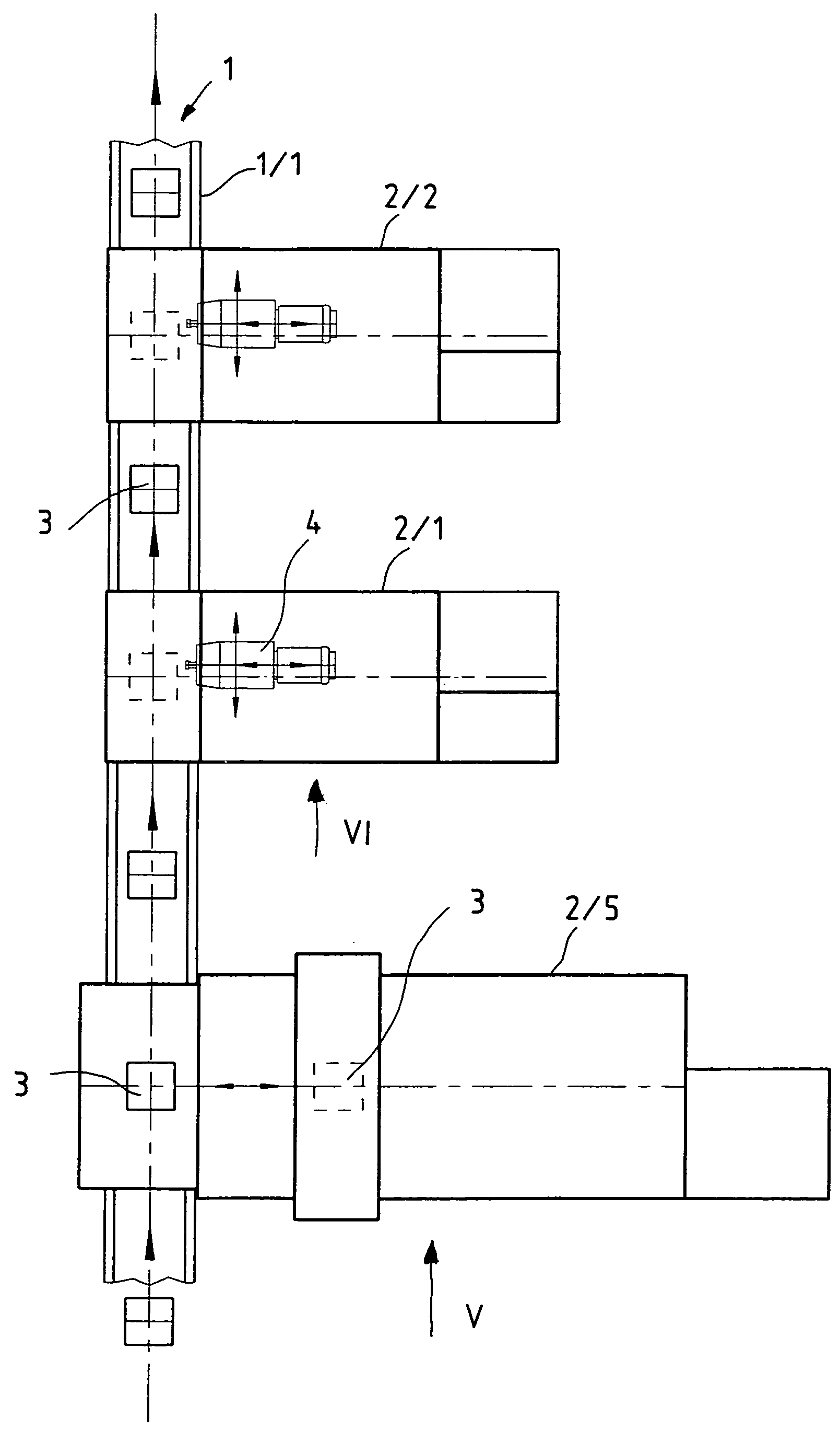
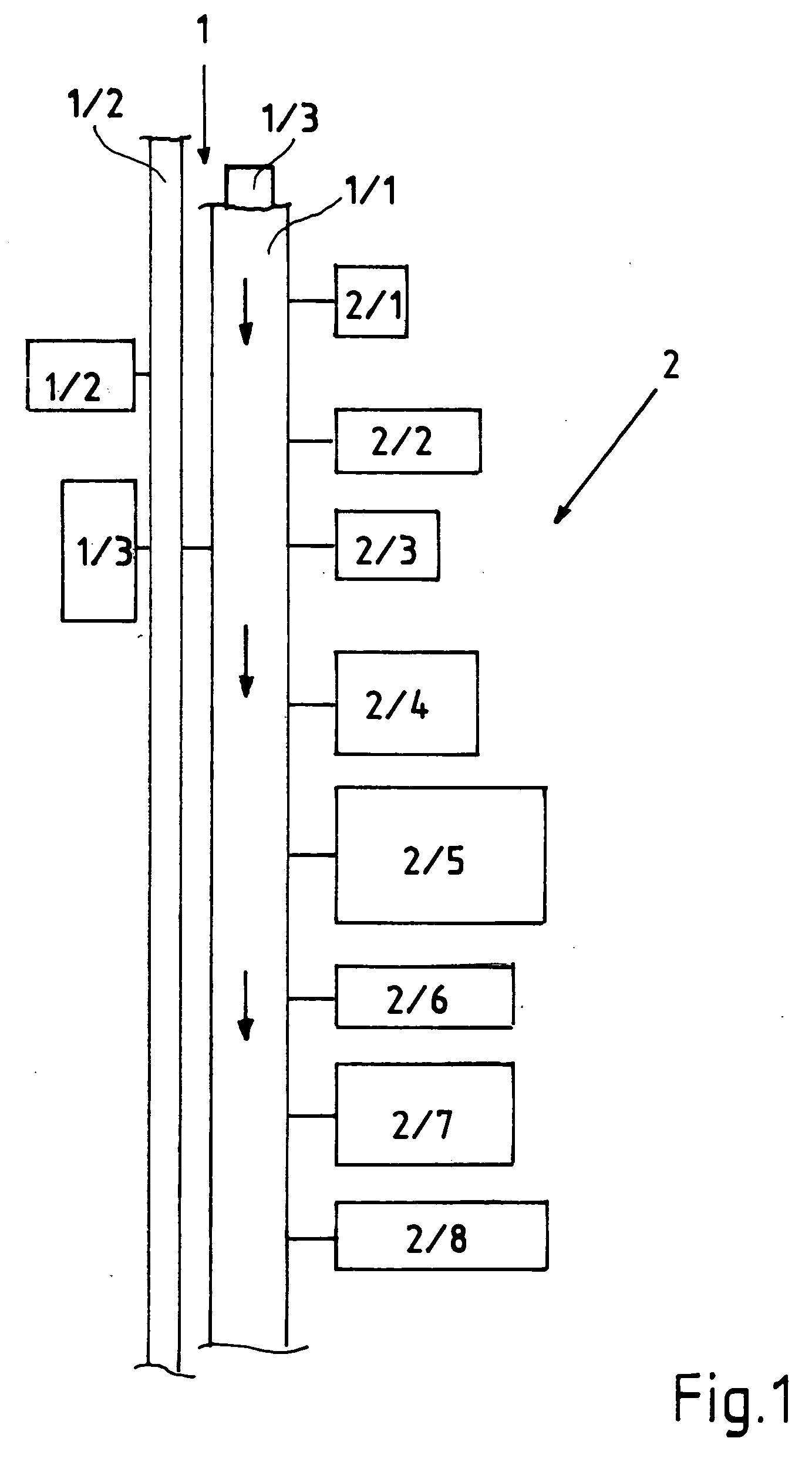
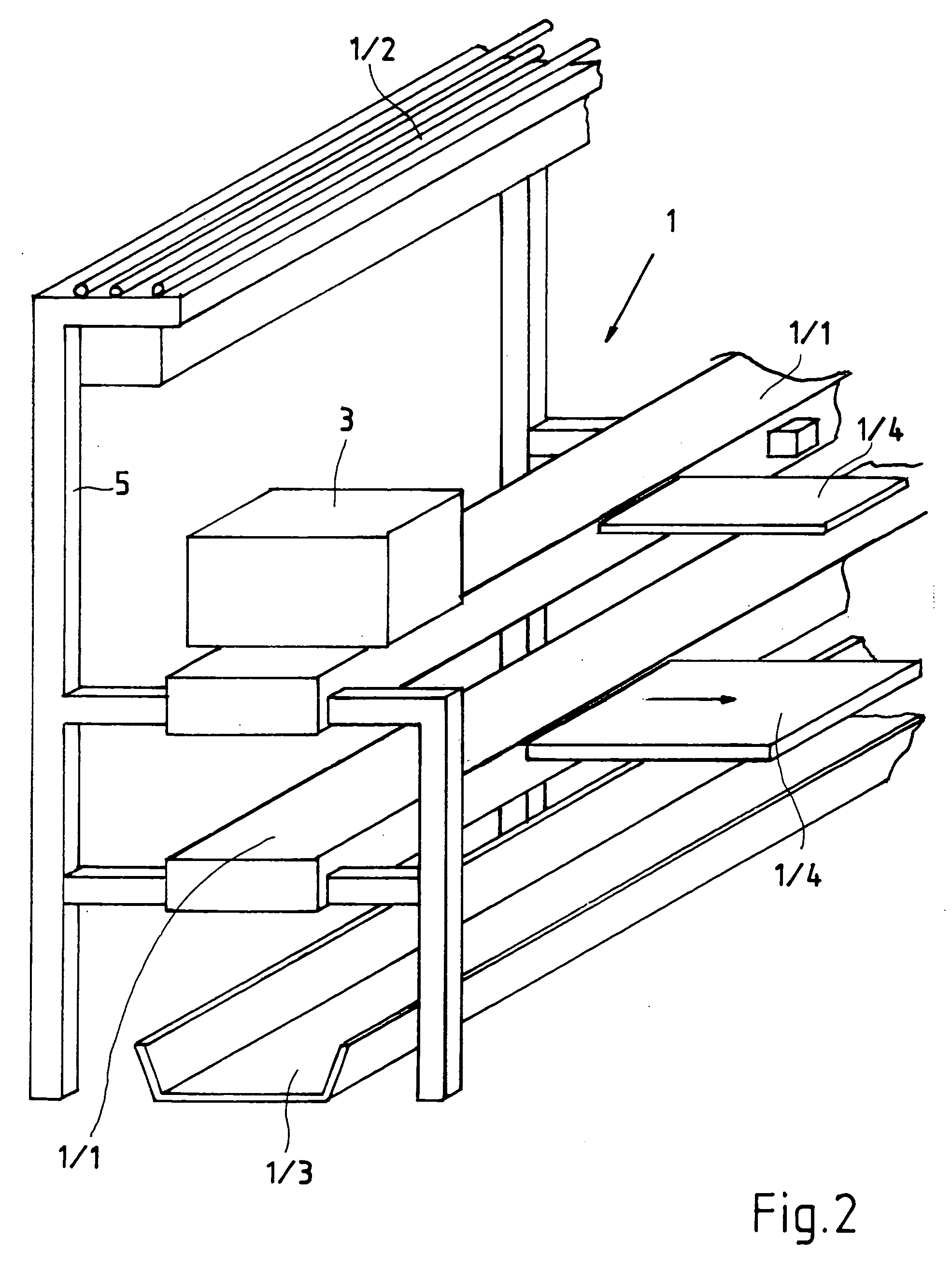
FIG. 1 shows a block diagram of an embodiment of the production system according to the invention. The arrow with the reference number 1 indicates the logistics module. The logistics module 1 consists of a conveying module 1 / 1, a supplying module 1 / 2, a disposal module 1 / 3 as well as a branching module 1 / 4 not shown in this drawing. The conveying module 1 / 1 may be here a roller conveyor, a slide guide, a friction roller conveyor or the like, which approaches, for example, work pieces 3 for machining to the process modules 2 and hands them over to them, if necessary, there via branching modules 1 / 4.

The supplying module 1 / 2 comprises in this embodiment two pieces. Thus, for example, it comprises a supplying line on which the individual conduits for the supply of the process modules 2 are arranged. The box with the reference number 1 / 2 indicates a supplying module which provides centrally, for example, the recycling of the process media like energy, gas, pressure and the like as descr...


PUM

PropertyMeasurementUnit
energyaaaaaaaaaa
pressureaaaaaaaaaa
lengthaaaaaaaaaa

Abstract

The invention refers to a production system, in particular machining line, which is formed, on the one hand, by one or more process modules which machine on work pieces and, on the other hand, is at least formed by one logistics module, and the logistics module provides a conveying of the work pieces, wherein the logistics module as a pre-assembled system module provides with and disposes of work pieces to a number of process modules, and the process module as system module can be connected to the logistics module.

Description

BACKGROUND OF THE INVENTION Production systems, in particular machining lines, respectively machining centers, are known. Production systems of this type are constructed in such a way that the work pieces which have to be machined on, respectively the components, are conveyed on a conveyor line to the single machine tools, respectively centers, and usually they are then conveyed through these. It is also known to combine continuous conveyor lines with machine tools in such a way that a transmitter, respectively a translator, is provided on the machine tool which conveys then the work pieces or components into the machine tool. For that purpose in the known solutions the conveyor line is interrupted. The machining center itself needs for that purpose suitable translators, respectively transmitters, means, which have to be integrated in the conveyor line. It is, for example, also known to equip single machining centers with a common translator. Parallel to a row of machining centers...

Claims


Application Information

Patent Timeline
Patent Type & Authority Applications(United States)
IPC IPC(8): B23Q41/02B23Q41/04
CPCB23Q41/02Y10T29/5196Y10T29/5124B23Q41/04
Inventor STAVE, HINRICHLUTZ, HEINRICH
Owner GROB WERKE BURKHART GROB E K
Learn More