X, Ku, K BAND OMNI-DIRECTIONAL ANTENNA WITH DIELECTRIC LOADING

Inactive Publication Date: 2010-06-03
BAE SYST INFORMATION & ELECTRONICS SYST INTERGRATION INC
View PDF18 Cites 9 Cited by
  • Summary
  • Abstract
  • Description
  • Claims
  • Application Information

AI Technical Summary

Benefits of technology

[0011]The above problems of biconical and similar antennas are solved by providing an X, Ku, and K-band omni-directional antenna with dielectric loading. Advantages of the new antenna are that it is small, very inexpensive, omni-directional, simply constructed, and easily reproduc

Problems solved by technology

Components, including antennas, can make these systems very expensive, however.
Broadband operation in the X, Ku, and K bands is desirable, but applicable biconical antennas are cost prohibitive and too large for applications.
They can cost thousands of dollars

Method used


Image

  • X, Ku, K BAND OMNI-DIRECTIONAL ANTENNA WITH DIELECTRIC LOADING
  • X, Ku, K BAND OMNI-DIRECTIONAL ANTENNA WITH DIELECTRIC LOADING
  • X, Ku, K BAND OMNI-DIRECTIONAL ANTENNA WITH DIELECTRIC LOADING

Examples


Example

[0022]Embodiments of the antenna are very small (one fortieth 1 / 40th of a cubic inch), have good azimuth coverage from at least +10 degrees to at least +70 degrees elevation, and have extremely wide bandwidth from approximately 7.5 to approximately 26 GHz. They are very low cost and very simple to connect to a transmit / receive microwave apparatus. Embodiments have vertical polarization.

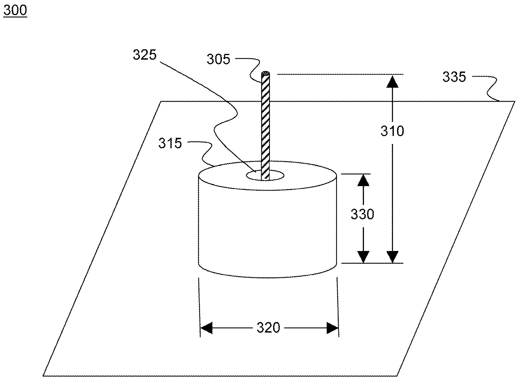
[0023]FIG. 3 is a simplified schematic illustration 300 of an embodiment of an X, Ku, K-band omnidirectional antenna with dielectric loading. Conductor 305 has a length 310 of 0.387 inch and a diameter of 0.050 inch. Dielectric resonator 315 has an outer diameter 320 of 0.290 inch and inner diameter 325 of 0.102 inch. Its height 330 is 0.151 inch. Dielectric resonator 315 embodiments are made of aluminum oxide Al2O3, but other dielectrics may be used. Dielectric resonator 315 provides loading to the antenna system. Ground plane 335 can incorporate a backside 50 ohm coaxial feed (not shown). In embodim...


PUM


Abstract

An X, Ku, and K-band omni-directional antenna with dielectric loading is disclosed. It comprises a conductor with a loading dielectric resonator and a ground plane. Broad frequency coverage from 7.5 to 26 GHz includes uniform azimuthal coverage from +10 to +70 degrees. The antenna can be used generally in microwave communications including Digital Radio Frequency Tags (DRaFTs) communicating with airborne and satellite platforms.

Description

STATEMENT OF GOVERNMENT INTEREST[0001]The invention was made with United States Government support under Contract No. W15P7T-05-C-P627 awarded by the U.S. Army. The United States Government has certain rights in this invention.FIELD OF THE INVENTION[0002]This invention relates to microwave antennas and, more particularly, to the utilization of an X, Ku, and K band omnidirectional antenna with dielectric loading.BACKGROUND OF THE INVENTION[0003]Broadband microwave communications provide the opportunity for miniaturized systems generally unobtainable at lower frequencies. Components, including antennas, can make these systems very expensive, however.[0004]Radio frequency communication with air and space platforms provides the opportunity to remotely track objects over large distances. Military operations especially have a need for tracking technology for air-to-ground Combat Identification (CID). This generally includes microwave communications.[0005]As an example, a Digital Radio Fre...

Claims


Application Information

Patent Timeline
IPC IPC(8): H01Q9/32
CPCH01Q9/32H01Q9/0485
Inventor PERKINS, III, THOMAS O.
Owner BAE SYST INFORMATION & ELECTRONICS SYST INTERGRATION INC
Why Eureka
Try Eureka