Tension-torque-transmission element for a fenestron blade and method for producing it

a technology of fenestron blade and transmission element, which is applied in the direction of propulsive elements, marine propulsion, vessel construction, etc., can solve the problems of lack of damage tolerance and inacceptably short service life, and achieve the effects of wide width, long service life and high quality

Active Publication Date: 2014-09-16
AIRBUS HELICOPTERS DEUT GMBH
View PDF24 Cites 13 Cited by
  • Summary
  • Abstract
  • Description
  • Claims
  • Application Information

AI Technical Summary

Benefits of technology

[0006]In the tension-torque-transmission element stated in the introduction this object is met in that it is layered in a fibre-reinforced composite design comprising several layers of a textile fabric. The invention thus moves away from the teaching of the state of the art, according to which the tension-torque-transmission element is to comprise metal, in particular for reasons of load resistance. Nor does the invention pursue an integrated design of the tension-torque-transmission element in the rotor blade. Instead, the invention pursues the principle of producing the tension-torque-transmission element separately on the one hand, and in a fibre-reinforced composite design on the other hand. The tension-torque-transmission element thus has a significantly lighter weight than a comparable component of metal. Furthermore, its production-, maintenance- and installation effort are reduced when compared to that of the separate tension-torque-transmission elements described above. Nonetheless, production of the tension-torque-transmission element in a fibre-reinforced composite design promises a long service life and damage-tolerant behaviour, which is of decisive importance in the operation of a rotor. Moreover, designs in fibre-reinforced composite are economical, are easily reproducible, and involve low-risk production methods. In addition, the separate tension-torque-transmission element can with little effort at least be subjected to visual inspection both after its production and during subsequent maintenance procedures, i.e. can easily be checked.
[0031]According to an advantageous embodiment of the method according to the invention, in a step d) the connecting eyes in the tension-torque-transmission element are subsequently drilled or milled in a direction perpendicular to the plane of extension of the tension-torque-transmission element. Each connecting eye and the surrounding laminate are dimensioned as a hole-face and are subjected to load. As a result of it having been produced later, the laminate is undisturbed right up to the hole-face. This also reveals the later production of the connecting eye, in that as a result of later drilling the hole-face displays completely undisturbed fibre layers that are placed compactly one above the other. Consequently the tension-torque-transmission element can be produced in the smallest-possible dimensions because there is no need to calculate overmeasure for any fibre layers that have a lower load-bearing capacity and that are disturbed.

Problems solved by technology

However, this design has been shown to have an unacceptably short service life and lacks damage tolerance so that as a less practicable solution it is rarely used.

Method used


Image

  • Tension-torque-transmission element for a fenestron blade and method for producing it
  • Tension-torque-transmission element for a fenestron blade and method for producing it
  • Tension-torque-transmission element for a fenestron blade and method for producing it

Examples


Embodiment Construction

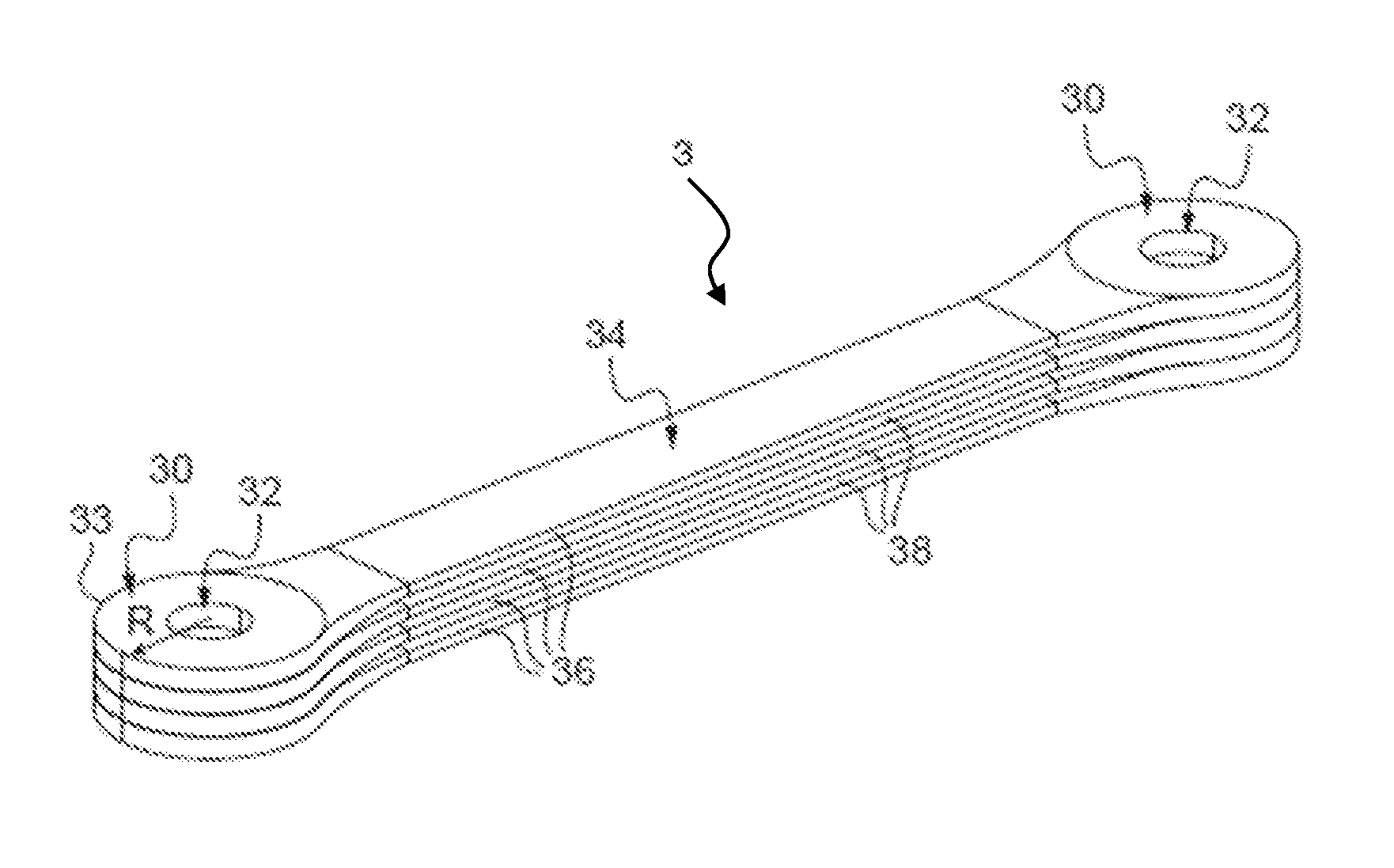
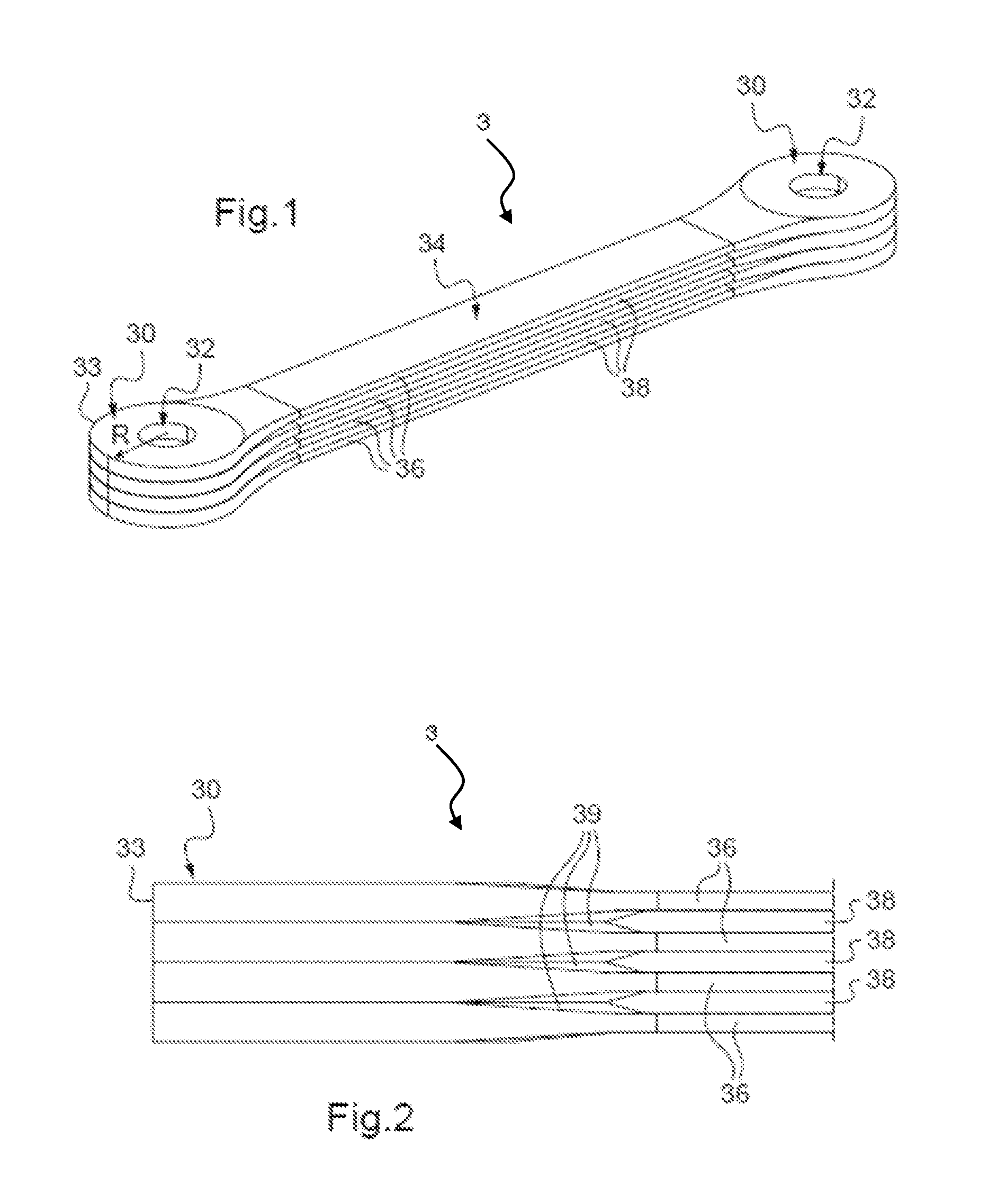
[0039]FIG. 1 shows a tension-torque-transmission element 3 in a fibre-reinforced composite design. It comprises a central elongated rectangular torque-transmission element 34 which on its two narrow sides makes a transition to connecting sections 30. The connecting sections 30, which in horizontal projection are more than semi-circular in shape, comprise circular connecting eyes 32 that have a constant margin space R towards the margin 33 of the respective connecting section 30.

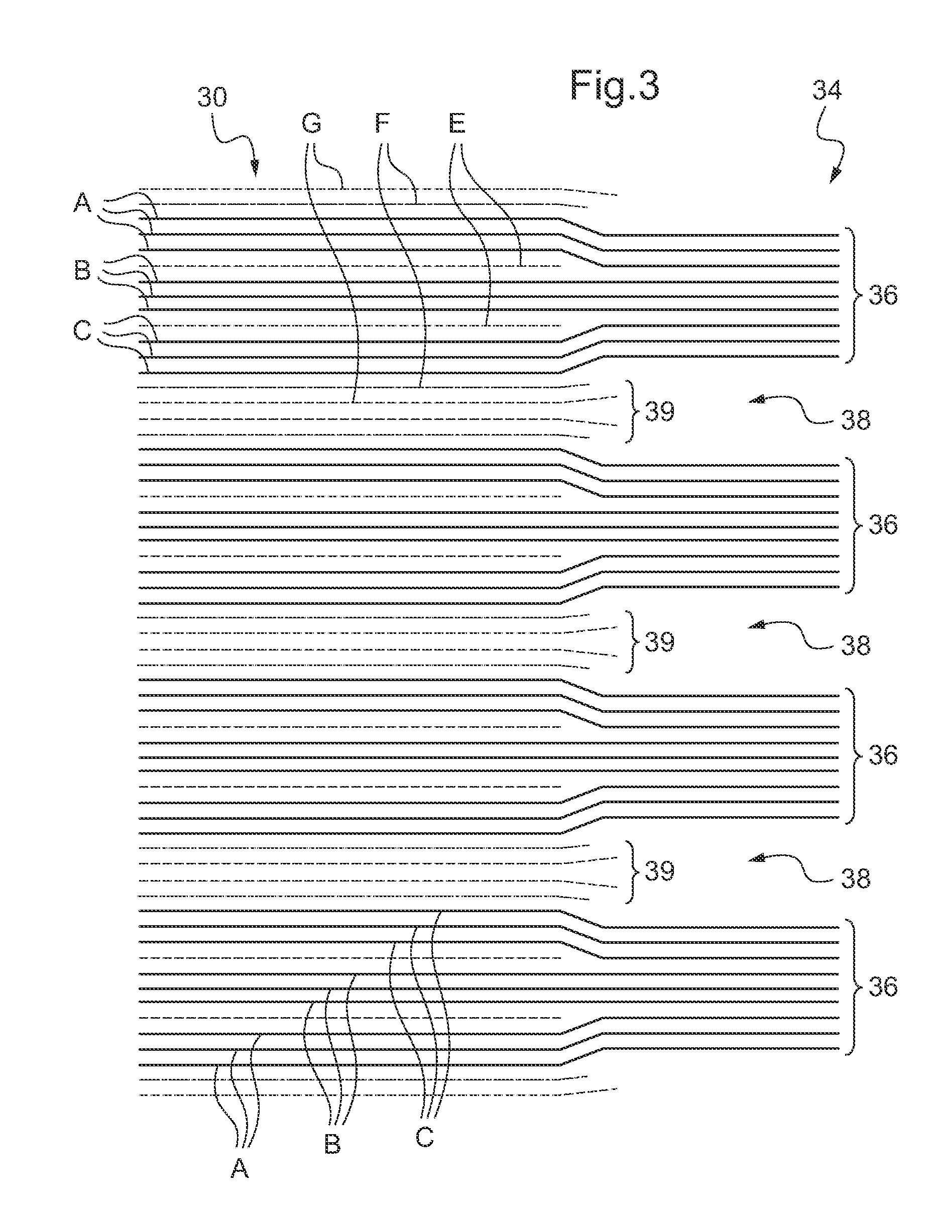
[0040]The torque-transmission element 34 comprises four individual tape-shaped lamellae 36 that extend parallel to each other and are stacked, which lamellae enclose slots 38 of the same nature. The lamellae 36 comprise several unidirectional fibre layers which extend right through, whose flow of the fibres is aligned in longitudinal direction of the tension-torque-transmission element 3. The lamellae 36, which are spaced apart from each other by slots 38, in the connecting sections 30 form a homogeneous laye...


PUM

PropertyMeasurementUnit
anglesaaaaaaaaaa
anglesaaaaaaaaaa
right-angleaaaaaaaaaa

Abstract

A tension-torque-transmission element (3; 3′; 4) for a rotor blade of a rotary wing aircraft (helicopter), in particular for a fenestron blade of a tail rotor, with a connecting section on the blade side and a connecting section (30; 30′; 40) on the axis side, with a connecting eye (32) on each connecting section, and with a torque-transmission section (34; 34′; 44) that connects the connecting sections (30; 30′; 40), is improved in that the tension-torque-transmission element (3; 3′; 4) is designed in a fiber-reinforced composite design including several layers (A to G) of a textile fabric. A method for producing such a tension-torque-transmission element (3; 3′; 4) is also described.

Description

CROSS-REFERENCE TO RELATED APPLICATIONS[0001]This application claims priority to European Application No. EP 09 400017.1 filed Apr. 29, 2009, the disclosure of which is hereby incorporated in its entirety by reference herein.FIELD OF THE INVENTION[0002]The invention relates to a tension-torque-transmission element for a rotor blade of a rotary wing aircraft or helicopter. Said tension-torque-transmission element can in particular be used for a fenestron blade of the tail rotor of a helicopter. The tension-torque-transmission element comprises a connecting section on the blade side, a connecting section on the axis-side, a connecting eye on each connecting section, and a torque-transmission section or spar that interconnects the connecting sections. Furthermore, the invention relates to a method for producing such a tension-torque-transmission element in a fibre-reinforced composite design.BACKGROUND OF THE INVENTION[0003]In DE 692 24 525 T2 in FIG. 2 a tension-torque-transmission el...

Claims


Application Information

Patent Timeline
Patent Type & Authority Patents(United States)
IPC IPC(8): F01D5/14B29C70/54B29D99/00B29L31/08B64C27/33B64C27/473
CPCB64C27/33B29D99/0025B29C70/545B64C2027/4736B29L2031/082Y10T29/49801B29C2793/0045B29L2031/06
Inventor KUNTZE-FECHNER, GERALDSCHULZ, MARTIN
Owner AIRBUS HELICOPTERS DEUT GMBH
Why Eureka
Try Eureka