Nuclide transmutation device and nuclide transmutation method

a nuclide and transmutation device technology, applied in nuclear reactors, nuclear explosives, greenhouse gas reduction, etc., can solve the problems of large-scale and high-cost apparatuses, difficult processing of long-lived radioactive nuclear fission products, and dramatic increase in the cost of nuclide transmutation

Inactive Publication Date: 2002-06-27
MITSUBISHI HEAVY IND LTD
View PDF0 Cites 9 Cited by
  • Summary
  • Abstract
  • Description
  • Claims
  • Application Information

AI Technical Summary

Benefits of technology

[0017] According to the nuclide transmutation device having the structure described above, a pressure differential in the deuterium between the one surface and the other surface of the structure body is provided in a state wherein the material that undergoes nuclide transmutation is bound to one of the surfaces of the structure body serving as a multilayer structure, and within the structure body a flux of deuterium from one surface side to the other surface side is produced, and thereby an easily reproducible nuclide transmutation reaction can be produced for the deuterium and the material that undergoes nuclide transmutation.
[0027] According to the nuclide transmutation device having the structure described above, a mixed layer that includes a material having a low work function is provided on the structure body that serves as the multilayer structure, and thereby the repeatability of the production of the nuclide transmutation reaction is improved.
[0028] According to the nuclide transmutation device having the structure described above, the production of the nuclide transmutation reaction can be further promoted by transmuting the material that undergoes nuclide transmutation to a nuclide having a similar isotope ratio composition.
[0030] According to the nuclide transmutation method described above, a pressure differential in the deuterium is provided between the one surface side and the other surface side of the structure body in a state in which the material that undergoes nuclide transmutation is bound to the one surface of the structure body that serves as the multilayer structure, and a flux of deuterium from the one surface side to the other surface side in the structure body is produced, and thereby the nuclide transmutation reaction is produced with good repeatability for the deuterium and the material that undergoes nuclide transmutation.
[0034] According to the nuclide transmutation method described above, the material that undergoes nuclide transmutation is transmuted to a nuclide having a similar isotopic ratio composition, and thereby the nuclide transmutation reaction can be promoted.

Problems solved by technology

However, long-lived radioactive nuclear fission products are difficult to process by neutron irradiation in a nuclear reactor and the like, and for example, for Sr-90, Cs-137 and the like, which have a small neutron interaction cross section, disposal processing using an accelerator is applied.
However, in the case of carrying out nuclide transmutation using a nuclear reactor or an accelerator, as in the disposal processes in the above-described examples of conventional technology, there are the problems in that large-scale and high cost apparatuses must be used, and the cost required for the nuclide transmutation increases drastically.
Furthermore, in the case of processing, for example, Cs-137, which is a long-lived radioactive nuclide fission product, when transmutating Cs-137 radiated from an electron power generator of about one million KW to another nuclide using an accelerator, there are problems in that the necessary power reaches one million KW and a high strength and large current accelerator become necessary, and thus efficiency is low.
In addition, in contrast to a thermal neutron flux of about 1.times.10.sup.14 / cm.sup.2 / sec in a nuclear reactor such as a light water reactor, the neutron flux necessary for nuclide transmutation of Cs-137, which has a small neutron interaction cross section, is about 1.times.10.sup.17-1.times.10.sup.18 / cm.sup.2 / sec, and there is the problem in that the necessary neutron flux cannot be attained.

Method used


Image

  • Nuclide transmutation device and nuclide transmutation method
  • Nuclide transmutation device and nuclide transmutation method
  • Nuclide transmutation device and nuclide transmutation method

Examples


example six seven eight na 430 25 16 56 (ppm) 0.08

6 0.005 0.003 0.011 (g) 2.3 .times. 10.sup.21 1.3 .times. 10.sup.20 8.4 .times. 10.sup.19 2.9 .times. 10.sup.20 (Atoms) Al <1 410 420 310 (ppm) <2 .times. 10.sup.-4 0.082 0.084 0.062 (g) <2 .times. 10.sup.18 1.8 .times. 10.sup.21 1.9 .times. 10.sup.21 1.4 .times. 10.sup.21 (Atoms)

[0187] As shown in Table 2, in the electrolyte solution 84 before the commencement of the experiments, the Na was at 430 ppm, and Al was equal to or less than the detection limit of 1 ppm.

[0188] In contrast, after the nuclide transmutation experiment, the Na became several tens of ppm, a value being one order lower, and the Al had become several tens of a ppm. The change in the electrolyte solution 84 after the commencement of the experiment carried out only electrolysis by providing current from the power source 81, and other materials were not introduced from the outside.

[0189] In addition, regarding the number of atoms (Atom, in Table 2), it could be confirmed that the decreased number of Na atoms fell f...

third embodiment

[0194] Below, the nuclide transmutation device and the nuclide transmutation method according to the present invention are explained with reference to the attached drawings.

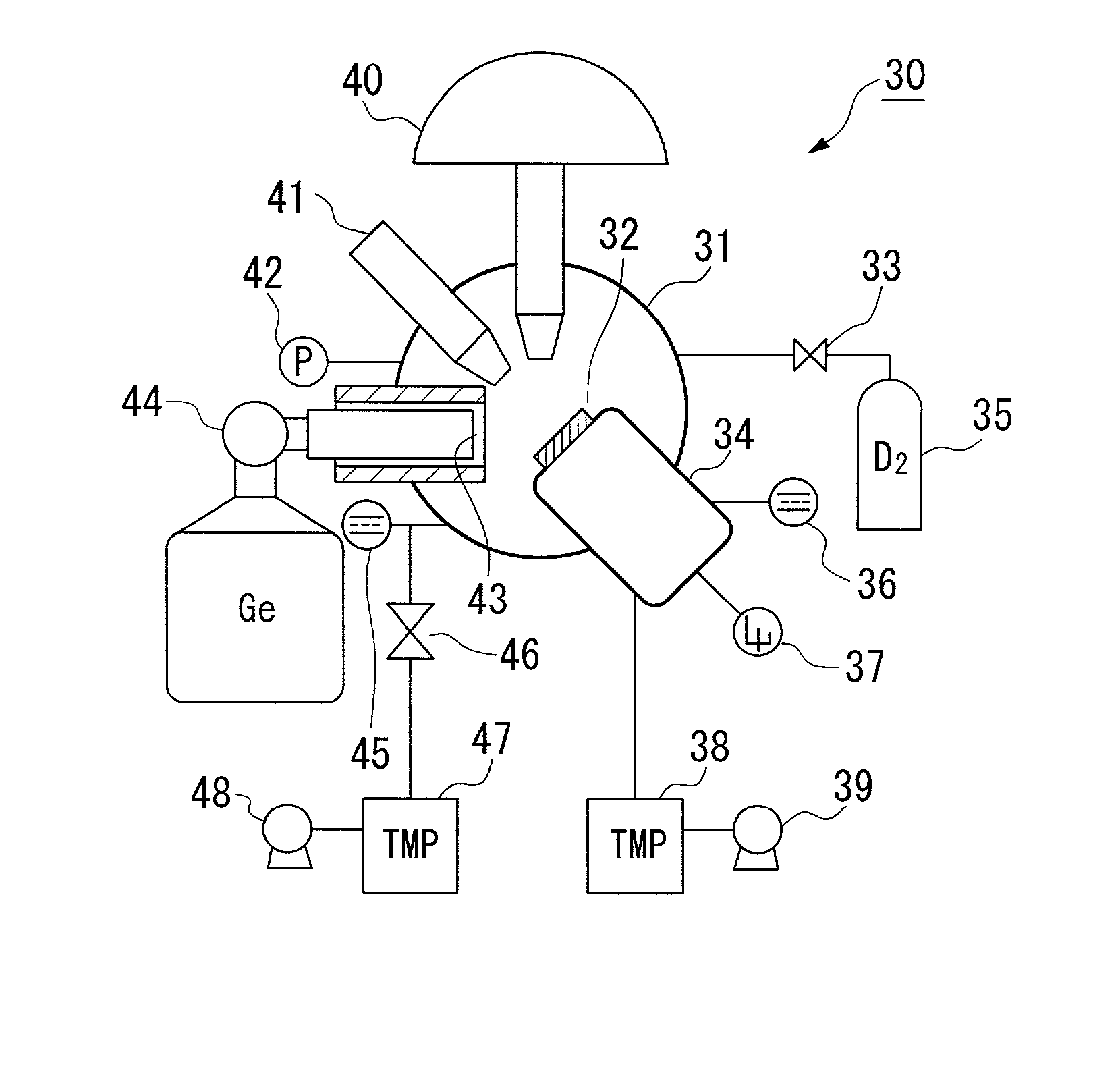
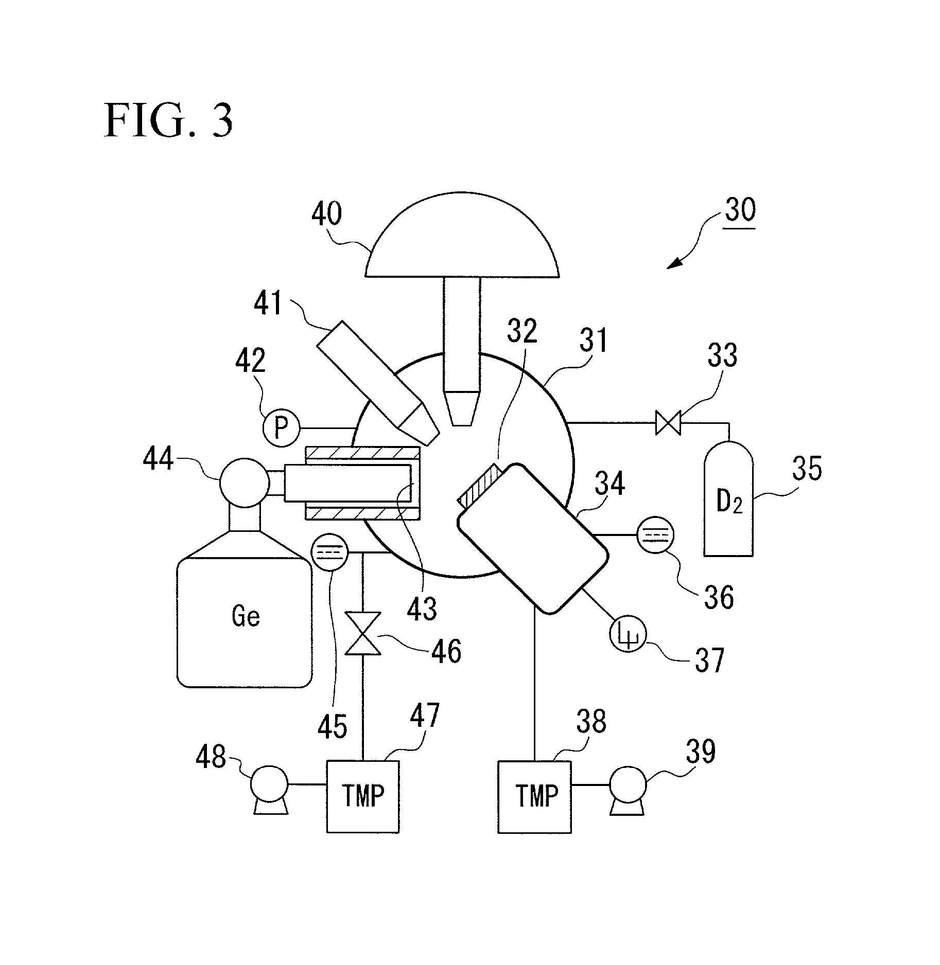
[0195] FIG. 22 shows a structure of the nuclide transmutation device 100 according to the third embodiment of the present invention.

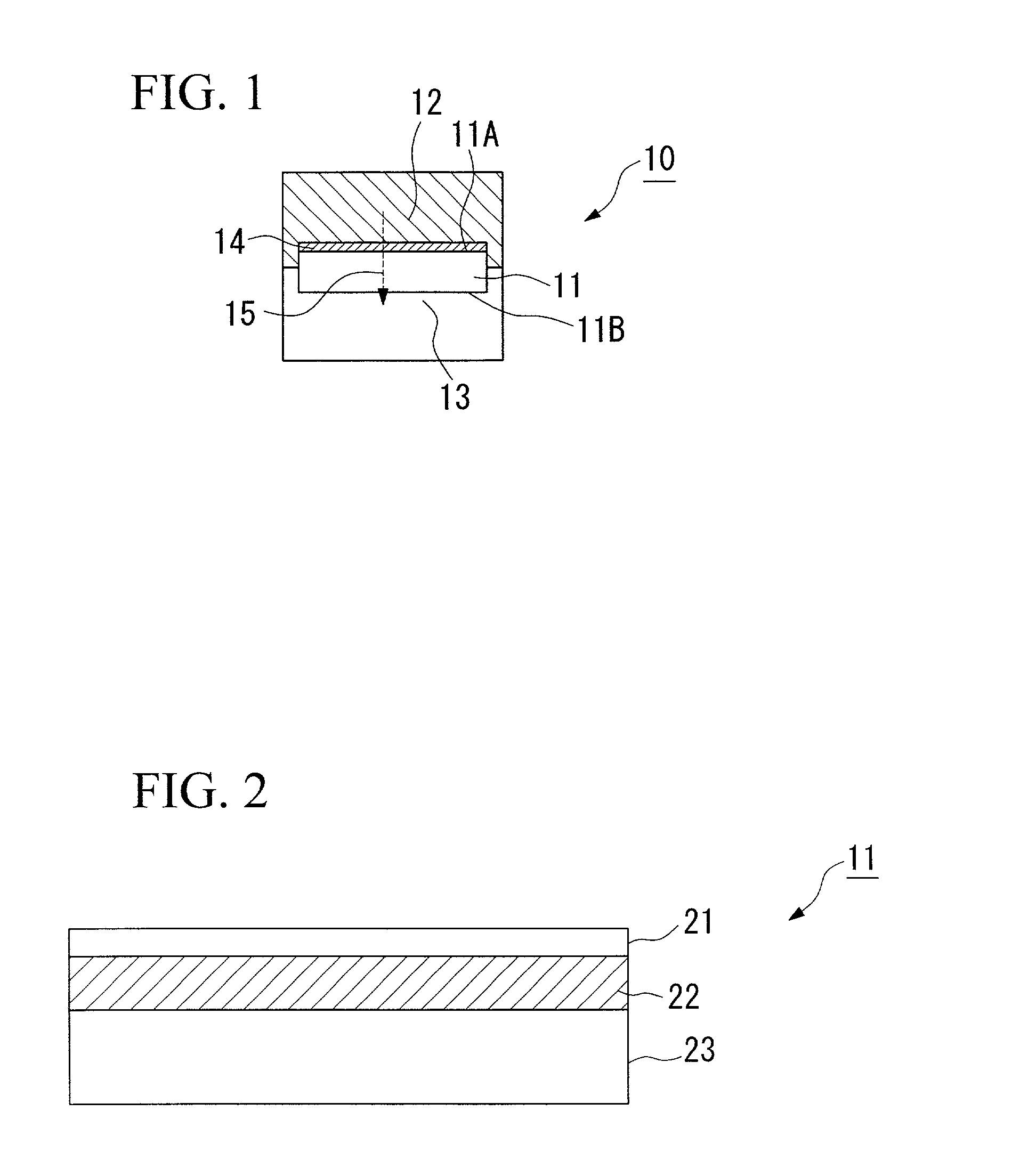
[0196] The nuclide transmutation device 100 according to this embodiment comprises a desorption chamber 101 having an interior that can be maintained in an airtight state, an absorption chamber 103, disposed inside of the desorption chamber 101 and having an interior that can be maintained in an airtight state through a multilayer structure body 102, a deuterium tank 106 for supplying deuterium into the absorption chamber 103 through a regulator valve 104 and a valve 105, a pressure meter 107 for detecting the inside pressure of the absorption chamber 103, a connecting pipe 109 for connecting the desorption chamber 101 and a absorption chamber 103 through a vacuum valve 108, a turbo-...

first embodiment

[0214] In addition, in spite of the fact that the present nuclide transmutation device and the multilayer structure body differ from the nuclide transmutation device 30 and the multilayer structure body both of the nuclide transmutation devices and multilayer structure bodies are confirmed to be able to carry out the nuclide transmutation such as from Cs to Pr successfully, which results in showing the substantial effectiveness of the present invention.

[0215] In addition, in the first embodiment, the second embodiment, and the third embodiment of the present invention described above, palladium (Pd) was used as the metal for absorbing the hydrogen, but the invention is not limited thereby, and a Pd alloy, or, for example, another metal that absorbs hydrogen, such as Ti, Ni, V, or Cu, or an alloy thereof can be used.

[0216] As explained above, according to the first aspect of the nuclide transmutation device of the present invention, nuclide transmutation can be carried out with a re...


PUM

PropertyMeasurementUnit
work functionaaaaaaaaaa
depthaaaaaaaaaa
widthaaaaaaaaaa

Abstract

The present invention produces nuclide transmutation using a relatively small-scale device. The device 10 that produces nuclide transmutation comprises a structure body 11 that is substantially plate shaped and made of palladium (Pd) or palladium alloy, or another metal that absorbs hydrogen (for example, Ti) or an alloy thereof, and a material 14 that undergoes nuclide transmutation laminated on one surface 11A among the two surfaces of this structure body 11. The one surface 11A side of the structure body 11, for example, is made a region in which the pressure of the deuterium is high due to pressure or electrolysis and the like, and the other surface 11B side, for example, is a region in which the pressure of the deuterium is low due to vacuum exhausting and the like, and thereby, a flow of deuterium in the structure body 11 is produced, and nuclide transmutation is carried out by a reaction between the deuterium and the material 14 that undergoes nuclide transmutation.

Description

[0001] 1. Field of the Invention[0002] The present invention relates to a nuclide transmutation device and a nuclide transmutation method associated, for example, with disposal processes in which long-lived radioactive waste is transmuted into short-lived radioactive nuclides or stable nuclides, and technologies that generate rare earth elements from abundant elements found in the natural world.[0003] 2. Description of the Related Art[0004] Conventional disposal processes are known that include, for example, methods in which large amounts of long-lived radioactive nuclides included in high level radioactive waste and the like are efficiently and effectively transmuted in a short time. Examples of these methods are those in which small amounts of nuclide are transmuted, such as heavy element synthesis by a nuclear fusion reaction using a heavy ion accelerator.[0005] These disposal processes are nuclide transmutation processes in which minor actinides such as Np, Am, and Cm included i...

Claims


Application Information

Patent Timeline
Patent Type & Authority Applications(United States)
IPC IPC(8): G21B3/00C23C30/00C25B1/00G21F9/00G21G1/04
CPCG21B3/002G21G1/04Y02E30/10
Inventor IWAMURA, YASUHIROITOH, TAKEHIKOSAKANO, MITSURU
Owner MITSUBISHI HEAVY IND LTD
Why Eureka
Try Eureka