Spray device

Inactive Publication Date: 2005-02-01
TECAN TRADING AG
View PDF15 Cites 15 Cited by
  • Summary
  • Abstract
  • Description
  • Claims
  • Application Information

AI Technical Summary

Benefits of technology

The present invention is based on the object of providing a simple aspirating and dispensing/spraying device for laboratory devices, particularly in a testing and/or processing system for chemical materials or material mixtures, which is not susceptible to malfunctions and reliably ensures uniform distribution of a defined liquid sample. This object is achieved by the aspirating and dispensing/spraying device as it is characterized in Claim 1. An aspirating and dispensing/spraying device for a laboratory device, particularly in a testing and/or processing system for chemical materials or material mixtures, is suggested having a tube—whose front end has an outlet opening for delivery of a liquid and to whose back end a liquid supply line is connected—, having a sleeve which encloses the tube at a distance and having a pressurized gas supply line for supplying pressurized gas into a space lying between the sleeve and the tube, the sleeve having a discharge opening on the front end in which the front end of the tube is positioned in such a way that an annular gap which ensures the release of pressurized gas remains free between the tube and the edge of the discharge opening. The aspirating and dispensing/spraying device according to the presen

Problems solved by technology

These types of aspirating and dispensing/spraying devices are spray devices and are subject to various disadvantages, which, above all, impair the possibilities for their use in the laboratory field.
Thus, it is not possible, particularly with changing pressures, to ensure uniform distribution of the liquid over a larger area, particularly if the openings are relatively large, so that the individual streams are not sufficiently dispersed.
On the other hand, if the openings are very small they clog easily, which in turn impairs the uniformity of the distribution or makes any proper functioning impossible.
In addition, these types of spray devices are relatively complicated and

Method used


Image

  • Spray device
  • Spray device
  • Spray device

Examples


Example

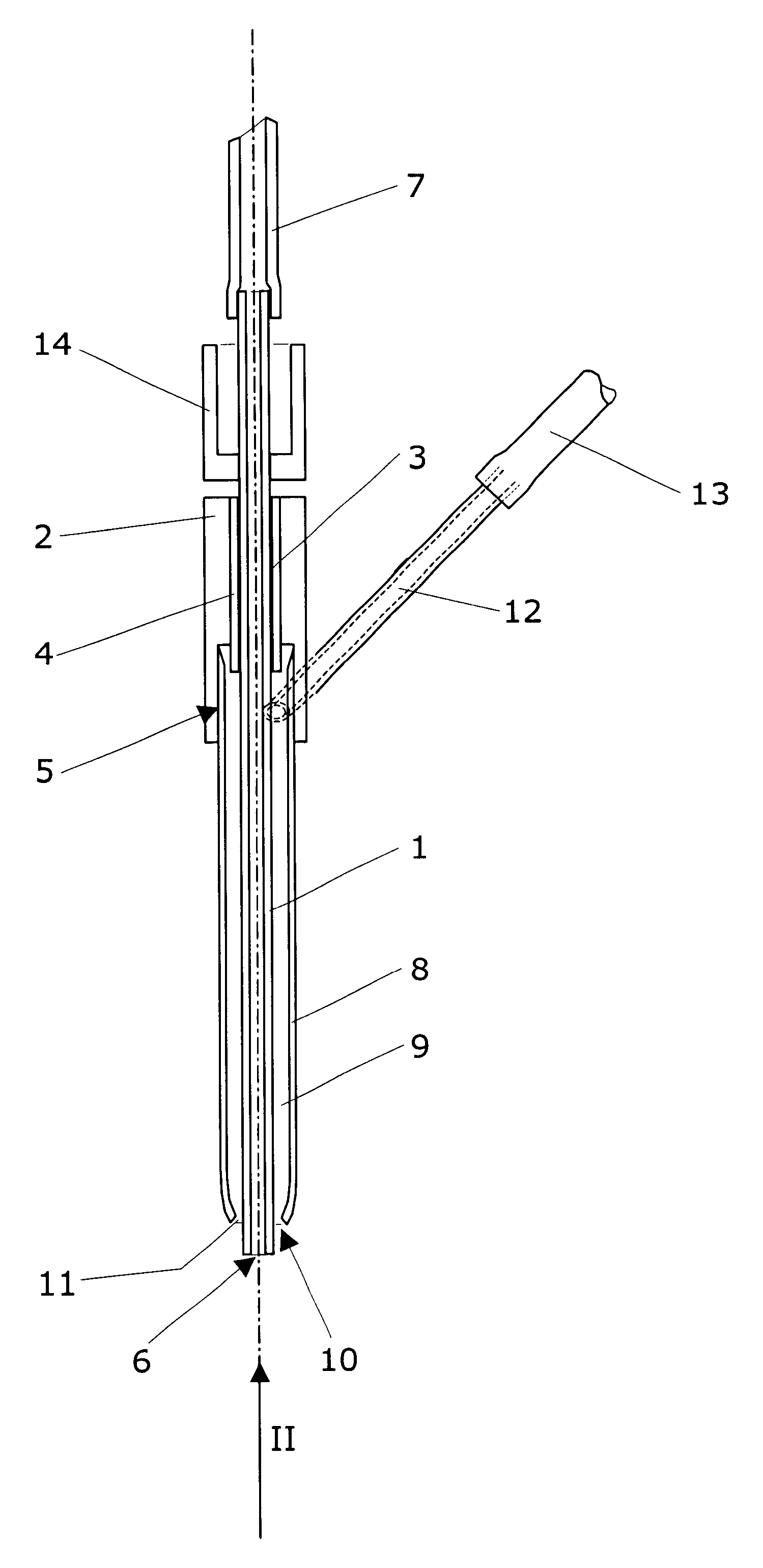
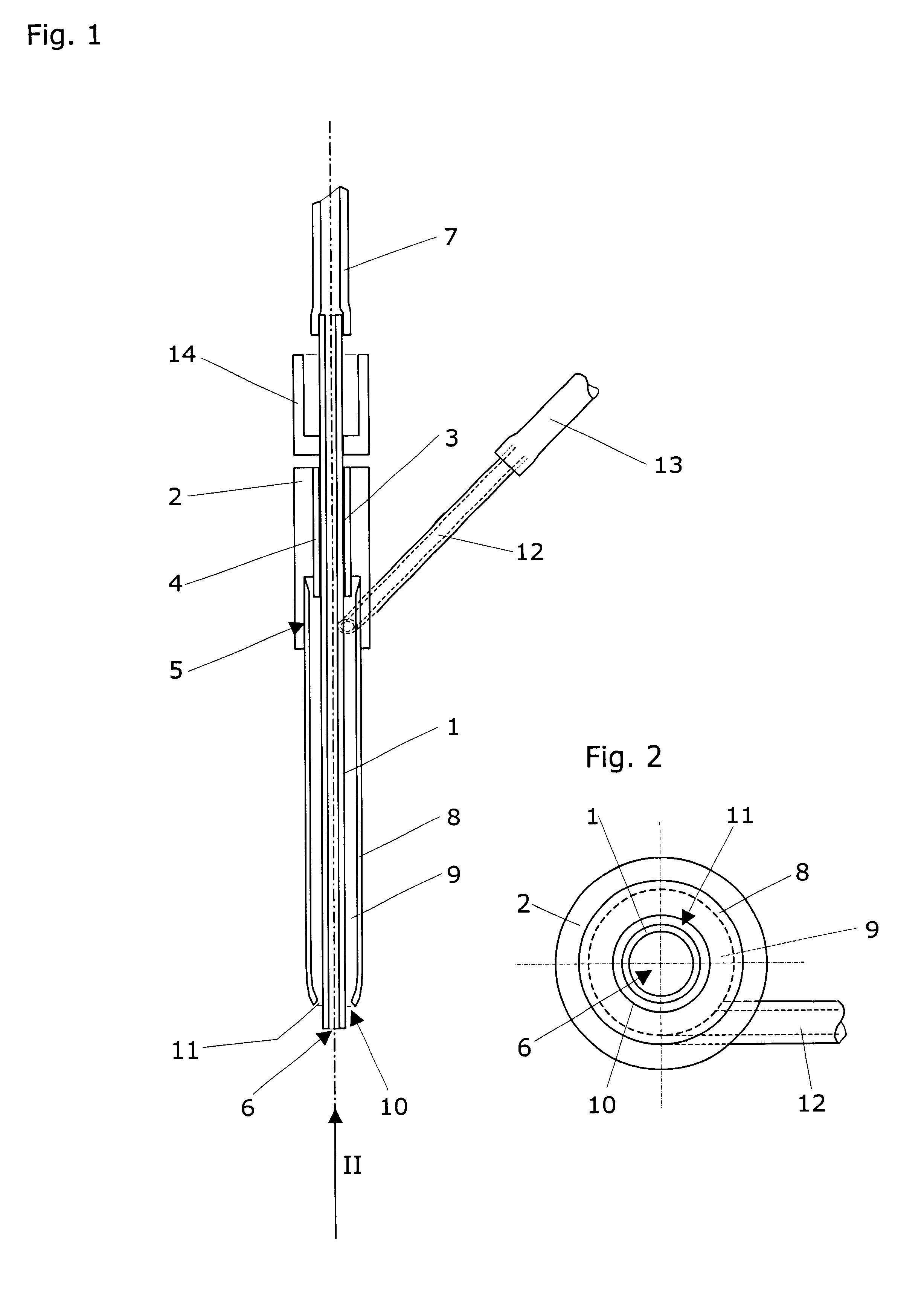
The aspirating and dispensing / spraying device has a tube 1, onto which an approximately cylindrical holder 2 is also screwed, an outer thread 3 on tube 1 engaging with the thread of a threaded bore 4 of holder 2 which receives it, which opens into a coaxial cylindrical recess 5 on the bottom of holder 2. The holder may therefore be displaced along tube 1 by rotation. Its forward end, which is further from recess 5, carries a outlet opening 6, while its back end, which lies above holder 1, adjoins a tube 7 which connects it to, for example, a liquid container and which is used as a liquid supply line.

A sleeve 8 is solidly anchored in recess 5 which is also implemented as essentially tubular and surrounds tube 1 coaxially at a distance, so that a space 9 approximately in the shape of a cylinder envelope lies between the inside of sleeve 8 and the outside of tube 1. Sleeve 8, and therefore space 9, narrow approximately conically toward the front end of tube 1 to a discharge opening 10,...


PUM


Abstract

In an aspirating and dispensing/spraying device, a holder is screwed onto a tube, connected to a liquid supply line, in such a way that it is displaceable along the tube by rotation. The tube is surrounded at a distance by a coaxial sleeve, which is solidly anchored in the holder, having a discharge opening on its front end, which is conically narrowed, whose edge surrounds the front end of the tube, which carries a outlet opening, separated by a narrow annular gap from the tube. The sleeve carries a connecting piece laterally, to which a pressurized gas supply line is connected and which discharges eccentrically into the space between the sleeve and the tube, so that pressurized gas flowing in receives angular momentum. When the gas flows out of the annular gap, it mixes intensively with the liquid coming out of the outlet opening and forms a discharge cone made of a fine, symmetrical aerosol with the liquid. This aspirating and dispensing/spraying device is simultaneously implemented as a pipette for aspirating liquids through the outlet opening of the tube's front end, said tube carrying a sensor near said outlet opening for detecting a liquid surface during pipetting.

Description

RELATED APPLICATION DATAThis application claims priority of the European patent application No. 01 810 415.8 filed on Apr. 27, 2001, the entire disclosure of which is incorporated herein by reference.FIELD OF THE INVENTIONThe present invention relates to an aspirating and dispensing / spraying device for a laboratory device, e.g. for a pipettor, in which the aspirating and dispensing / spraying device may be used. It may be used for keeping gels or membranes moist or also for spraying plants or plant parts, such as leaves, larva, etc., with diverse liquids.BACKGROUND OF THE INVENTIONAspirating and dispensing / spraying devices are known which are implemented like watering cans having small openings distributed over a surface. These types of aspirating and dispensing / spraying devices are spray devices and are subject to various disadvantages, which, above all, impair the possibilities for their use in the laboratory field. Thus, it is not possible, particularly with changing pressures, to ...

Claims


Application Information

Patent Timeline
IPC IPC(8): B05B7/06B05B7/10B01L3/02B05B7/02B05B7/12G01N1/36
CPCB01L3/0268B05B7/066G01N1/38B05B7/12B05B7/10
Inventor RYSER, DANIEL
Owner TECAN TRADING AG
Why Eureka
Try Eureka