Micro-combustion chamber heat engine

a heat engine and combustion chamber technology, applied in the field of micro-combustion chamber heat engines, can solve the problems of heat loss, unharnessed (wasted) work, frictional loss and unharnessed work, and all eight cylinders are constantly contributing to frictional loss,

Inactive Publication Date: 2005-02-24
RAY JAMES T
View PDF18 Cites 4 Cited by
  • Summary
  • Abstract
  • Description
  • Claims
  • Application Information

AI Technical Summary

Benefits of technology

[0011] It is an object of the present invention to overcome one or more of the problems described above.

Problems solved by technology

Among the disadvantages of such engines are inefficiencies caused by heat losses, frictional losses and unharnessed (wasted) work due to the reciprocation of each piston.
For example, in a eight cylinder engine, only one cylinder is producing power at any given moment while all eight cylinders are constantly contributing to frictional losses.
The reciprocation of each piston also results in unwanted vibration and noise.
In addition, due to the relatively low combustion temperatures in such reciprocating piston engines, excessive pollutants such as particulates and carbon monoxide are produced by these engines.
Furthermore, reciprocating piston engines require refined fuel such as gasoline made from cracking of oil that is performed in refineries and costly to produce.
Such engines also require complex fuel injection or carbureation systems, camshafts, electrical systems and cooling systems that can be expensive and difficult to maintain.

Method used


Image

  • Micro-combustion chamber heat engine
  • Micro-combustion chamber heat engine
  • Micro-combustion chamber heat engine

Examples


second embodiment

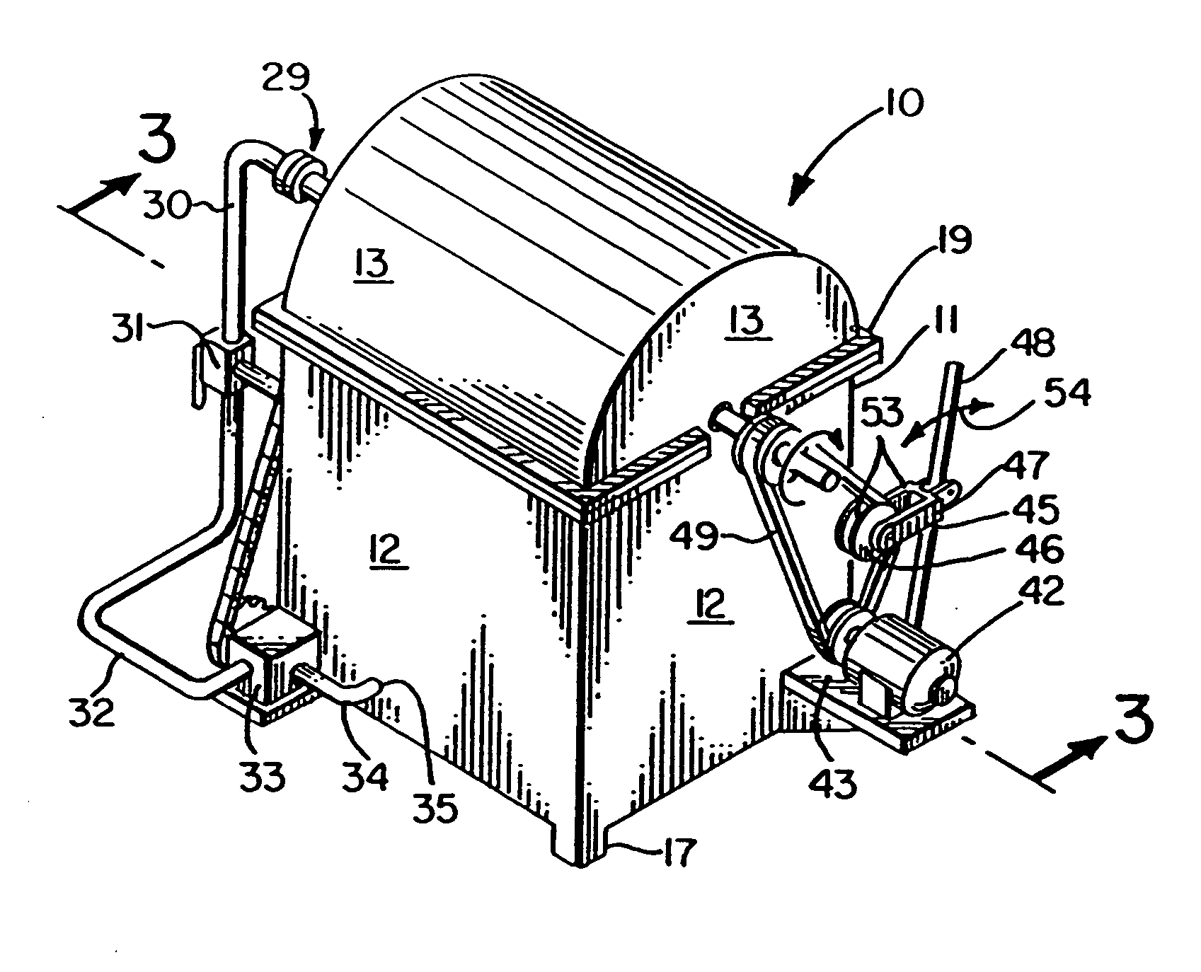
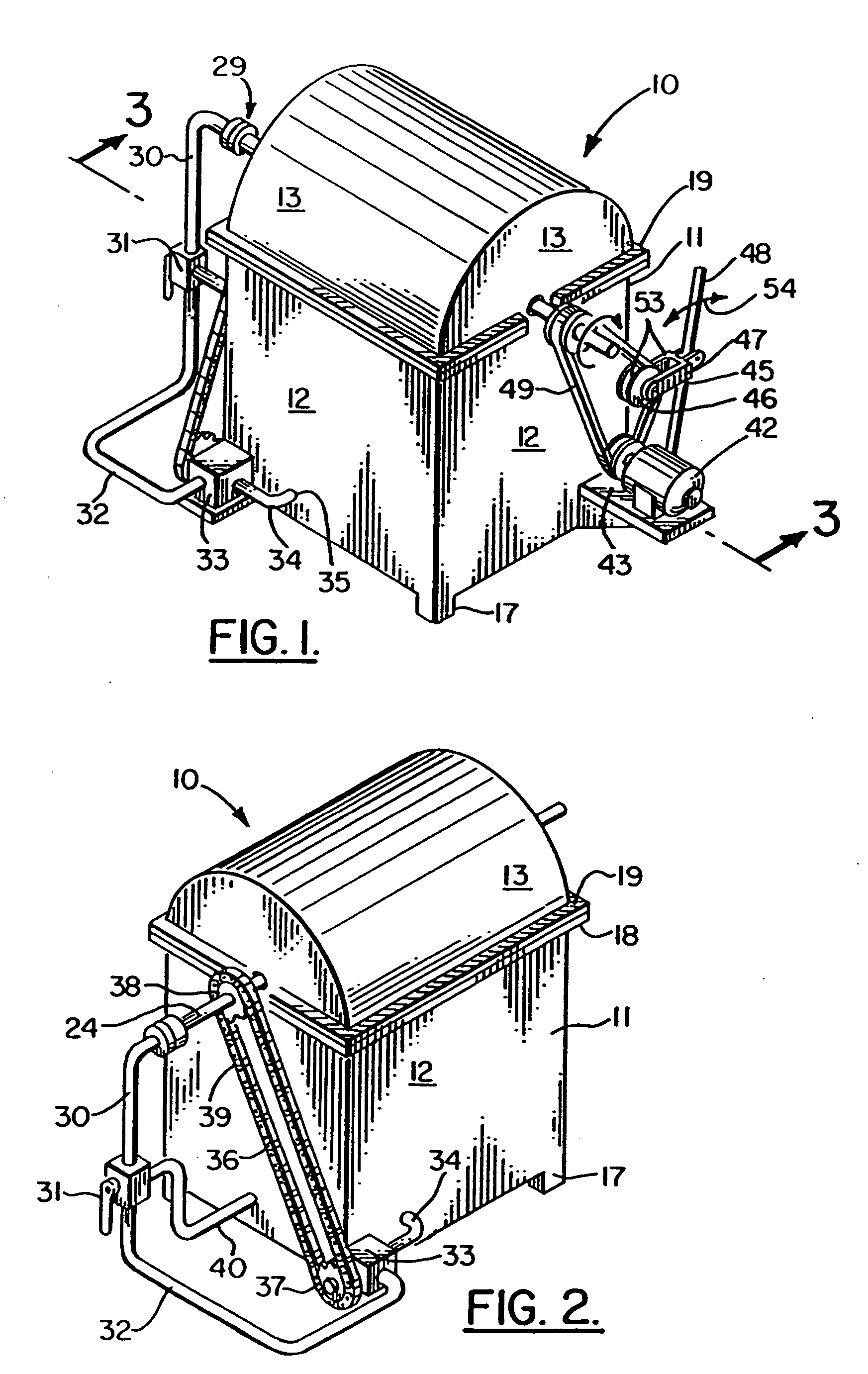
[0099]FIGS. 13-25 show the apparatus of the present invention designated generally by the numeral 110 in FIGS. 13, 14, and 15. Combustion engine 110 has an enlarged housing 111 with an interior 114. The housing 111 is comprised of upper and lower sections including a lower reservoir section 112 and an upper cover section 113.

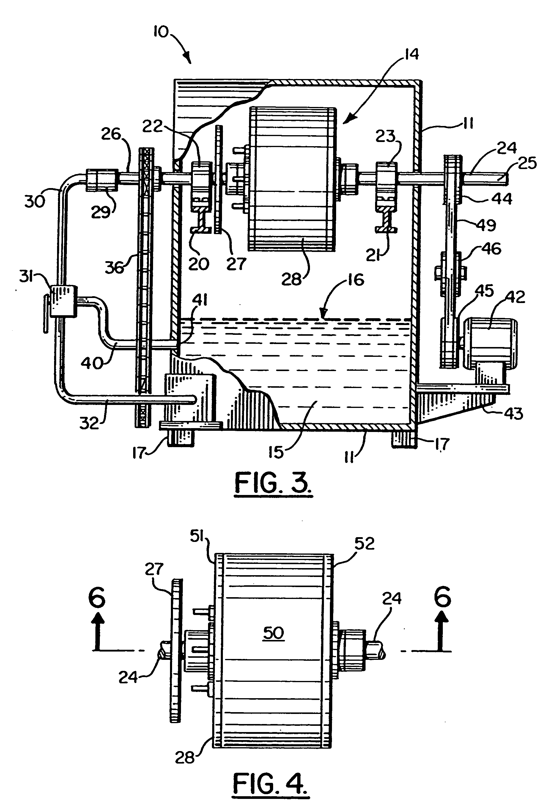
[0100] Fluid 115 is contained in the lower portion of reservoir section 112 as shown in FIG. 15, the fluid 115 having a fluid level 116 that is well below chamber 128 and drive shaft 124. The fluid can be any combustible fluid including automatic transmission fluid, hydraulic fluid, vegetable oil, corn oil, or peanut oil, for example. A plurality of feet 117 can be used to anchor housing 111 to a pedestal, mount, concrete base, or like structural support. A pair of sealing mating flanges 118, 119 can be provided respectively on housing sections 112, 113 to form a closure and seal that prevents leakage during use.

[0101] A pair of spaced apart transversely extend...

third embodiment

[0124]FIGS. 26-34 show the apparatus of the present invention designated generally by the numeral 210. Combustion engine 210 includes a housing 211 having a reservoir section 212 and a cover 213 that is removably attached to the reservoir section 212. The interior 214 of housing 211 is partially filled with fluid 215, the fluid level being indicated by arrow 216. Housing 211 can be provided with a plurality of feet 217.

[0125] In order to perfect a fluid seal between reservoir section 212 and cover 213, a pair of peripheral mating flanges 218, 219 are provided. The flange 218 is on the reservoir section 212. The flange 219 is on the cover section 213.

[0126] In FIG. 28, a pair of beams 220, 221 support bearings 222, 233 respectively. Bearings 222, 223 support drive shaft 224. Drive shaft 224 has a starter end portion 225 and a fluid inlet end portion 226. In this application, directions of rotations of various parts will be referred to as either clockwise rotation or counterclockwise...

fifth embodiment

[0147]FIGS. 37-47 show generally the apparatus of the present invention, designated generally by the numeral 315 in FIGS. 37, 38, and 39. Combustion engine 315 has an enlarged housing 316 with an interior 319. The housing 316 is comprised of upper and lower sections including a lower reservoir section 317 and an upper cover section 318.

[0148] Fluid 320 is contained in the lower portion of reservoir section 317 as shown in FIG. 39, the fluid 320 having a fluid level 321 that is well below chamber 333 and drive shaft 329. The fluid 320 can be most any combustible fluid including automatic transmission fluid, hydraulic fluid, vegetable oil, corn oil, peanut oil, for example.

[0149] A plurality of feet 322 can be used to anchor housing 316 to a pedestal, mount, concrete base, or like structural support. A pair of sealing mating flanges 323, 324 can be provided respectively on housing sections 317, 318 to form a closure and seal that prevents leakage during use.

[0150] A pair of spaced a...


PUM


Abstract

A combustion engine is provided having a rotating drive shaft and planetary gear sets that are linked to a rotating chamber, keyed to the drive shaft, to turbomachinery within the chamber. Fluid is fed to the chamber through an axial passage in the drive shaft and is compressed by a number of mechanisms, including set of pump blades, turbine and reaction blades initially driven by the drive shaft and its starter motor. Bubbles within the fluid are subjected to high pressures causing combustion to occur within the bubbles. Additional pressure created by the combustion of the bubbles drives the fluid to exert a net torque on the drive shaft through the gearing mechanism, thereby generating power.

Description

CROSS-REFERENCE TO RELATED APPLICATIONS [0001] This is a continuation-in-part of co-pending U.S. patent application Ser. No. 10 / 059,507, filed Jan. 29, 2002, which is a continuation-in-part of U.S. patent application Ser. No. 09 / 176,481 Oct. 21, 1998, which is a continuation-in-part of U.S. patent application Ser. No. 08 / 955,590, filed Oct. 22, 1997, which is incorporated herein by reference.STATEMENT REGARDING FEDERALLY SPONSORED RESEARCH OR DEVELOPMENT [0002] Not applicable REFERENCE TO A MICROFICHE APPENDIX [0003] Not applicable BACKGROUND OF THE INVENTION [0004] 1. Field of the Invention [0005] The present invention relates generally to an engine that produces energy through a process known as Cavitation and Associated Bubble Dynamics, and specifically to a method and apparatus for a combustion engine that uses bubbles within a fluid as the combustion chamber and for providing the combustion thereof. More particularly, the present invention relates to combustion-type engines tha...

Claims


Application Information

Patent Timeline
Patent Type & Authority Applications(United States)
IPC IPC(8): F02C3/14F02C3/16
CPCF02C3/16F02C3/24F02C3/22
Inventor RAY, JAMES T.
Owner RAY JAMES T
Why Eureka
Try Eureka