Brush seal

Inactive Publication Date: 2005-02-24
MTU AERO ENGINES GMBH
View PDF15 Cites 38 Cited by
  • Summary
  • Abstract
  • Description
  • Claims
  • Application Information

AI Technical Summary

Benefits of technology

[0009] At least the support element and/or the cover element of the bristle housing is/are made of plastic according to the present invention. This offers the advantage of reduced weight compared to a metallic support element and cover element. Furthermore, support elements and cover elements made of plastic are easier to join than support elements and cover elements made of metal. This allows brush seals to be manufactured more cost-effectively.
[0010] According to an advantageous refinem

Problems solved by technology

Brush seals made of metal are heavy in weig

Method used


Image

  • Brush seal
  • Brush seal
  • Brush seal

Examples


Embodiment Construction

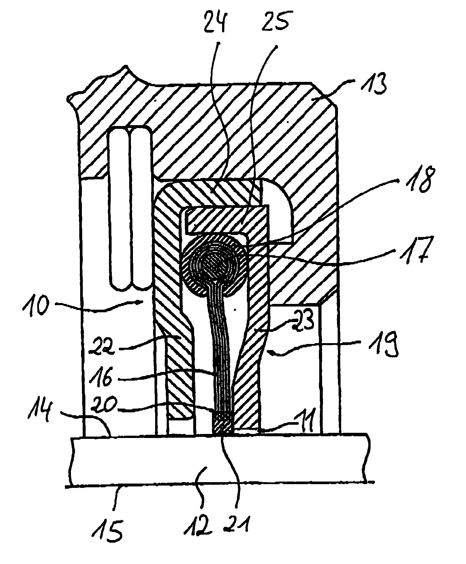
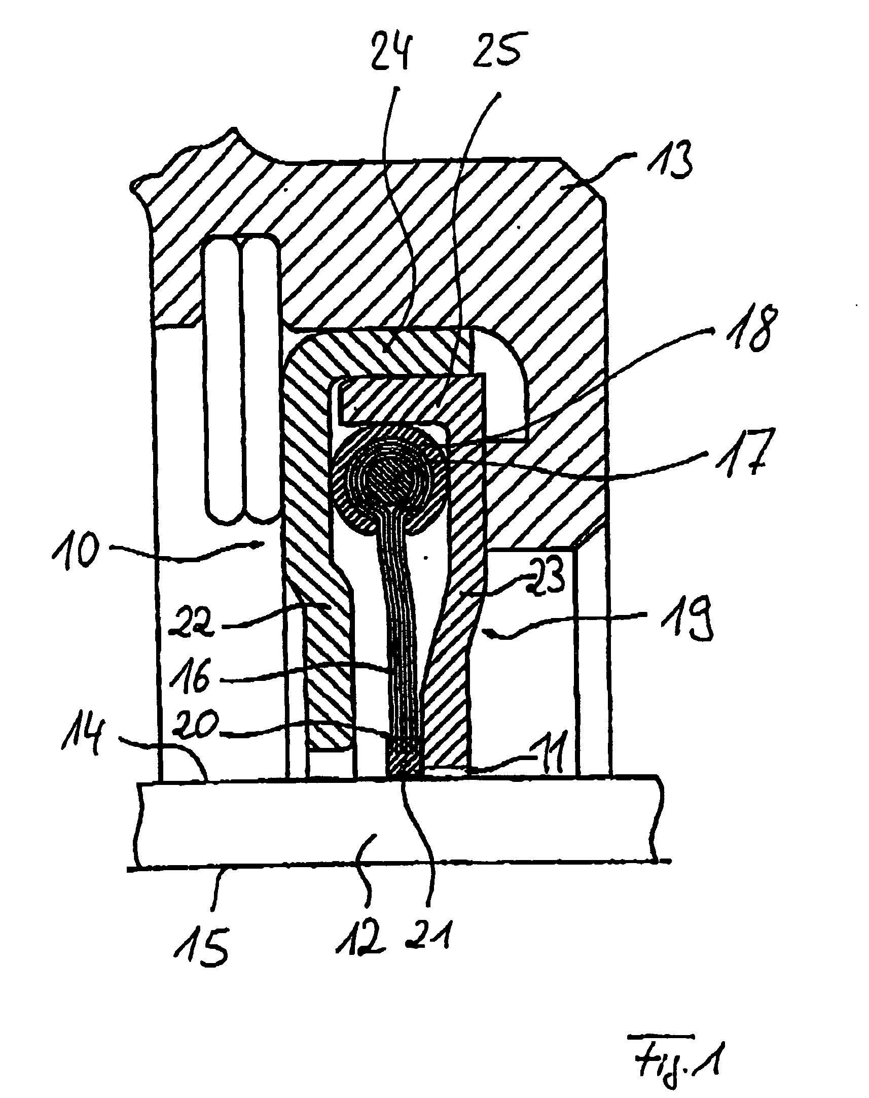
[0016]FIG. 1 shows a schematic cross-sectional view of a first exemplary embodiment of brush seal 10 of the present invention. Brush seal 10 is used for sealing a gap 11 between a rotor 12 and a stationary stator 13. In FIG. 1, a peripheral surface of rotor 12 is designated by reference number 14 and a central axis of the same by reference number 15. Such brush seals 10 are used, for example, in stationary gas turbines and aircraft propulsion units.

[0017] Brush seal 10 has a plurality of bristles 16. Bristles 16 are wound around a wire-shaped core element 17 having a round cross section and secured to core element 17 by a clamping element 18. Clamping element 18 has a C-shaped cross section.

[0018] The unit composed of bristles 16, core element 17, and clamping element 18 is situated in a bristle housing 19. In the exemplary embodiment shown, bristles 16 are essentially made of steel, each bristle forming an essentially straight line oriented radially with respect to rotor 12. In t...


PUM


Abstract

A brush seal has a bristle housing formed by a cover element and a support element. A plurality of bristles, which are wound around a core element and secured to the core element by a clamping element are positioned in the bristle housing. At least one of the support element and the cover element of the bristle housing are made of plastic.

Description

[0001] Priority is claimed to German Patent Application No. DE 103 37 867.7, filed on Aug. 18, 2003, the entire disclosure of which is incorporated by reference therein. [0002] The present invention relates to a brush seal for providing a non-hermetic seal, in particular between a stator and a rotor, having a bristle housing. BACKGROUND [0003] There are many applications in which two parts, namely a stator and a rotor, which rotate against one another, are to be sealed non-hermetically against one another. Such an application is, for example, sealing of an annular gap between the stator and rotor of a hydraulic machine, a gas turbine in particular, with a gas flowing through the gap. Brush seals are known in the related art for non-hermetic sealing of annular gaps between two components rotating with respect to one another. For example, German Patent Document DE 199 62 316 C2, related to U.S. Pat. No. 6,695,314, both of which are incorporated by reference herein describes brush seal...

Claims


Application Information

Patent Timeline
IPC IPC(8): H01R39/24H01R39/50H02K5/10H02K5/124
CPCF16J15/3288H01R39/24H02K5/124H02K5/10H01R39/50F01D11/001
Inventor BEICHL, STEFANGAIL, ALFONSHUPPERTZ, THOMAS
Owner MTU AERO ENGINES GMBH
Why Eureka
Try Eureka