Eureka AIR delivers breakthrough ideas for toughest innovation challenges, trusted by R&D personnel around the world.

Anisotropic touch screen element

Inactive Publication Date: 2005-02-24
ATMEL CORP
View PDF48 Cites 211 Cited by
  • Summary
  • Abstract
  • Description
  • Claims
  • Application Information

AI Technical Summary

Benefits of technology

The invention blends some of the features of unpatterned 4-electrode elements together with striped elements and mathematical compensation to arrive at a new classification of anisotropic 2DxT element, or simply, a ‘striped element’. This invention addresses the deficiencies of previous 2DxT approaches and is very low in cost, using as it does conventional processes and materials.
Further objects of the invention are to provide for a sensor having high reliability, a sealed surface, low power consumption, and the ability to be controlled and sensed directly using off-the-shelf microcontrollers and non-exotic drive electronics.

Problems solved by technology

Capacitive touch screens in particular are prized for their robustness against damage, but suffer from high costs and the need for exotic construction materials.
Many types of 2DCT are known to suffer from geometric distortion characterized as ‘pin cushion’ or ‘hyperbolic’ or ‘parabolic’, whereby the reported coordinate of touch is in error due to electrical effects on the sensing surface.
These methods have been found to be very difficult to develop and replicate, and they are prone to differential thermal heating induced errors and production problems.
Very small amounts of localized error or drift can cause substantial changes in coordinate response.
The low resistance of the patterned edge strips causes problems with the driver circuitry, forcing the driver circuitry to consume more power and be much more expensive than otherwise.
The unintended resistance causes a slight amount of pin cushion in the response.
The method is particularly suited to touch pads for mouse replacement but does not scale well to higher sizes.
The Allen method requires large scale integration and high numbers of connection pins.
The methods disclosed by Babb are complex and involve ‘80 coefficients’ and fourth order polynomials, the coefficients of which must be determined through a rigorous and time-consuming calibration procedure.
In tests supervised by the instant inventor, it has been found that 6th order polynomials are required to produce accuracy levels that are acceptable in normal use, and that the result is still highly prone to the slightest subsequent variations post-calibration due to thermal drift and the like.
Furthermore, the method of numerical correction requires high-resolution digital conversions in order to produce even modest resolution outputs.
The extra expense and power required of the amplifier system and ADC can be prohibitive in many applications.

Method used


Image

  • Anisotropic touch screen element
  • Anisotropic touch screen element
  • Anisotropic touch screen element

Examples


Embodiment Construction

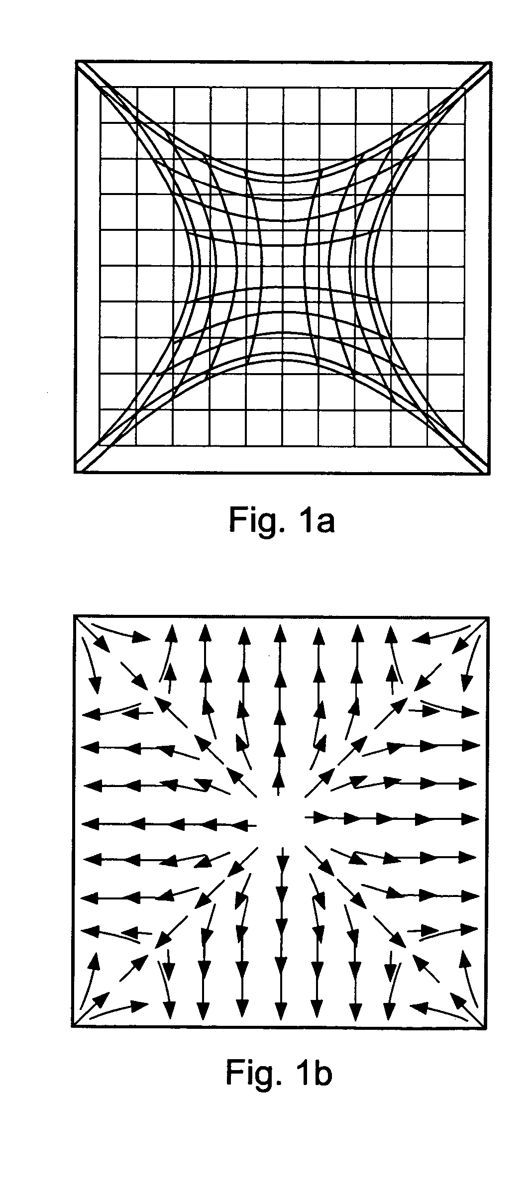
FIGS. 1a and 1b show the prior art for 2DxT technology prior to the use of correction hardware or algorithms. The pin cushion effect of FIG. 1a is well understood. It arises from the current sharing of capacitance-induced flows from the point of touch to the four connection points; the effect is seen in both 2DCT's and in 2DRT 5-wire touch screens which rely on a galvanic version of the same voltage gradients as a 2DCT, but with a flexible ‘pickoff’ cover sheet that deflects and connects to the 2DRT under pressure. The pin cushion effect in these elements increases as the location of touch becomes more distant from all connection points, along an edge; it is at its worst at the centers of the screen edges. As shown in FIG. 1b, the current flows establish vectors that introduce a graduated distortion with position, resulting in a parabolic curvature of reported location. The vectors are generally non-orthogonal. Instead the angle and magnitude of correction vary wildly depending on t...


PUM


Abstract

A touch sensitive position sensor for detecting the position of an object in two dimensions is described. The position sensor has first and second resistive bus-bars spaced apart with an anisotropic conductive area between them. Electric currents induced in the anisotropic conductive area by touch or proximity flow preferentially towards the bus-bars to be sensed by detection circuitry. Because induced currents, for example those induced by drive circuitry, flow preferentially along one direction, pin-cushion distortions in position estimates are largely constrained to this single direction. Such one-dimensional distortions can be corrected for very simply by applying scalar correction factors, thereby avoiding the need for complicated vector correction.

Description

BACKGROUND OF THE INVENTION The invention pertains to 2-dimensional touch sensing surfaces operable by a human finger, or a stylus. Example devices include touch screens and touch pads, particularly those over LCDs, CRTs and other types of displays, or pen-input tablets, or encoders used in machinery for feedback control purposes. Descriptions of pen or touch input to a machine date back to at least 1908, as embodied in patent DE 203,719 [1]. Touch screens and pointing devices have become increasingly popular and common not only in conjunction with personal computers but also in all manner of other appliances such as personal digital assistants (PDAs), point of sale (POS) terminals, electronic information and ticketing kiosks, kitchen appliances and the like. These devices are evolving continuously into lower priced products and as a result, there is a need for ever lower production cost while maintaining high levels of quality and robustness. Capacitive touch screens in particul...

Claims


Application Information

Patent Timeline
IPC IPC(8): G06F3/033G06F3/045
CPCG06F3/045
Inventor PHILIPP, HARALD
Owner ATMEL CORP
Why Eureka
Eureka Blog
Learn More