Imaging lens and illumination system

a technology of illumination system and imaging lens, applied in the field of optical imaging, can solve the problems of large, complex, expensive, difficult to visualize or photograph the interior structure of the human eye (i.e., the ocular fundus), and the conventional fundus imaging system is large, heavy, and difficult to achiev

Inactive Publication Date: 2005-02-24
THE ARIZONA BOARD OF REGENTS ON BEHALF OF THE UNIV OF ARIZONA
View PDF7 Cites 57 Cited by
  • Summary
  • Abstract
  • Description
  • Claims
  • Application Information

AI Technical Summary

Benefits of technology

[0011] Another object of the present invention is to provide a fundus imaging system which is less complex and bulky compared to the traditional fundus imaging systems Still another object of the present invention is to provide a fundus imaging system in which the imaging system images an indirectly illuminated portion of the eye such as the ocular fundus by illuminating directly other portions such as the crystalline lens and cornea.
[0012] Correspondingly, one problem with incorporating illumination and imaging in the same optics is back reflections from surfaces. Back reflections typically cause an out-of-focus spot to be formed over the top of recorded image. The advantage for using the same optics is a compact imaging system. Thus, the present invention presents configurations that eliminate back reflections, but keep imaging and illumination properties acceptable.
[0013] According to one aspect of the present imaging system, there is provided a baffle to prevent light from the annular light emitter from striking center of objective lens and back reflecting into image recorder. The objective lens forms an intermediate image of retina and the coupling lens couples this intermediate image into the digital camera optics.
[0020] In another embodiment of the present invention, a novel computer readable medium contains program instructions for execution on a computer system. The program instructions, when executed by the computer system, cause the computer system to image an object by controlling light emission from an annular light emitter arranged concentrically with an optical axis for illuminating the object, and capturing the image of the object from light directed to the object from the annular light emitter, reflected from a surface of the object, and imaged onto an image recorder.

Problems solved by technology

Visualizing or photographing interior structures of the human eye (i.e., the ocular fundus) is difficult because the entrance pupil of the eye is limited to a diameter of around 10 mm.
Such fundus cameras in either handheld, mounted, or desktop configurations must accommodate the light source and the associated beam forming and imaging optical elements described above for illumination and imaging, making conventional fundus imaging systems large, heavy, complex, and expensive.
This approach while simpler than that shown in FIG. 1A suffers due to inadvertent light scattering in the eye.
Further, the amount of illumination that can be directed into the eye is limited in this approach, and the illumination and imaging pathways overlap.

Method used


Image

  • Imaging lens and illumination system
  • Imaging lens and illumination system
  • Imaging lens and illumination system

Examples


Embodiment Construction

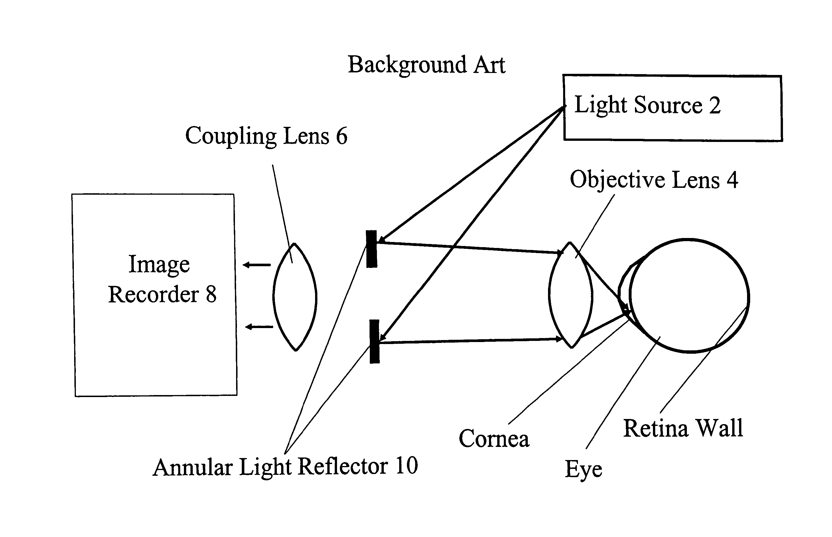
[0035] Referring now to the drawings, wherein like reference numerals designate like or corresponding parts throughout the several views, and more particularly to FIG. 2, FIG. 2 illustrates problems in illuminating the interior structure of an eye, especially a human eye. As shown in FIG. 2, light reflecting from the retinal surface must pass through the cornea and the fundus lens and pupil behind the cornea before then passing through the objective lens 4 and coupling lens 6 to the image recorder 8. While coatings such as anti-reflective coatings can be added to the external lens (i.e. the objective lens 4 and coupling lens 6) to minimize image transmission losses, the complexities of the reflections and transmissivity of the cornea, pupil, and fundus lens are beyond control of the eye examiner.

[0036]FIG. 3 illustrates one approach of the present invention used to reduce glare by indirectly illuminating portions of the eye such as for example the ocular fundus by illuminating dire...


PUM


Abstract

An imaging system and method for imaging an object, where an objective lens directs light to the object, a coupling lens receives light reflected from a surface of the object and transmitted through the objective lens, and focuses the reflected light as an image of the object, and an annular light emitter arranged concentrically with an optical axis of the objective lens and the coupling lens emits to the objective lens the light directed to the object.

Description

CROSS REFERENCE TO RELATED APPLICATIONS [0001] This application is related to U.S. Provisional Application Ser. No. 60 / 455,297, filed on Mar. 17, 2003, entitled “A Fundus Imaging Lens and Illumination System,” the entire contents of which are incorporated herein by reference.BACKGROUND OF THE INVENTION [0002] 1. Field of the Invention [0003] This invention relates to the field of optical imaging to which it has general application and particularly is related to optometry and the diagnostic equipment used therein, and more specifically ophthalmic imaging equipment and methods for examining the eye and other suitable parts of the body. [0004] 2. Description of the Related Art [0005] Visualizing or photographing interior structures of the human eye (i.e., the ocular fundus) is difficult because the entrance pupil of the eye is limited to a diameter of around 10 mm. Through this image area, both illumination pathways and imaging pathways must co-exist but not create glare. Traditional m...

Claims


Application Information

Patent Timeline
Patent Type & Authority Applications(United States)
IPC IPC(8): A61BA61B3/00A61B3/10A61B3/12A61B3/14A61B3/15
CPCA61B3/156A61B3/10A61B3/14
Inventor MILLER, JOSEPH MARIONSCHWIEGERLING, JAMES THEODORE
Owner THE ARIZONA BOARD OF REGENTS ON BEHALF OF THE UNIV OF ARIZONA
Why Eureka
Try Eureka