Optical transmission system

a transmission system and optical transmission technology, applied in the field of optical transmission systems, can solve the problems of inability to increase the transmission distance, difficult long-distance transmission of osc signals, and large loss of osc signals, and achieve high-quality long-distance optical transmission and prevent inappropriate operations

Inactive Publication Date: 2005-02-24
FUJITSU LTD
View PDF8 Cites 54 Cited by
  • Summary
  • Abstract
  • Description
  • Claims
  • Application Information

AI Technical Summary

Benefits of technology

[0019] The present invention is made in view of the above problems, and the object of the present invention is to provide an optical transmission system w

Problems solved by technology

Since it is impossible to raise the transmission levels of the OSC signals more than +10 dBm above levels at which an anti-hazard measure becomes necessary, or lower the reception levels in an O/E (opto-electric conversion) module provided on the receiver side below a minimum reception level, conventionally, long-distance transmission of the OSC signals is difficult.
In the case where the transmission line is a single mode fiber (SMF), and wavelengths on the shorter-wavelength side of main signals (e.g., around the wavelength of 1,510 nm) are allocated to OSC signals, loss in the OSC signals is great, and therefore it is impossible to increase the transmission distance.
Therefore, in this case, an error is detected by an OSC receiver unit provided in

Method used


Image

  • Optical transmission system
  • Optical transmission system
  • Optical transmission system

Examples


Embodiment Construction

[0031] Embodiments of the present invention are explained below with reference to drawings.

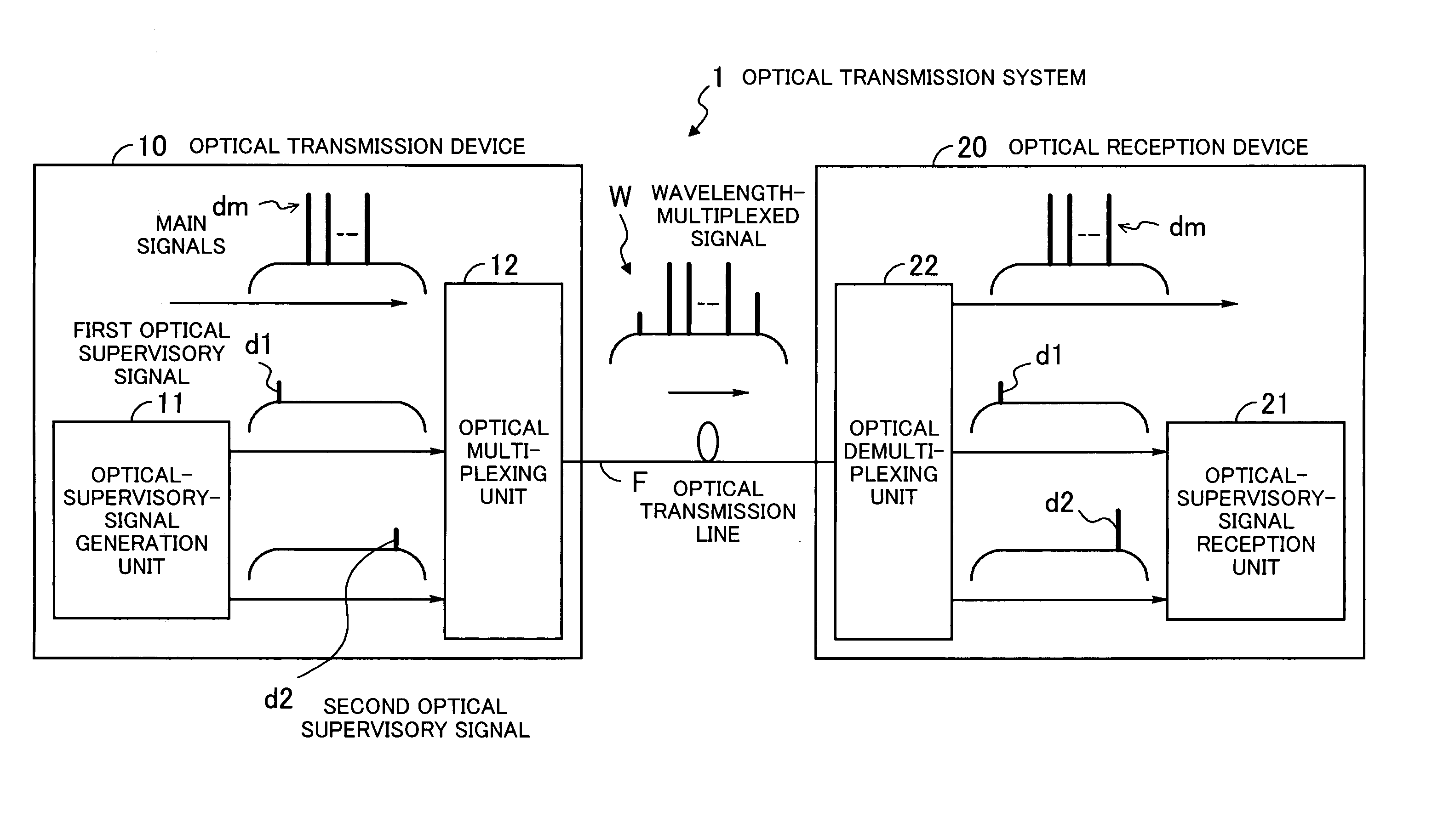
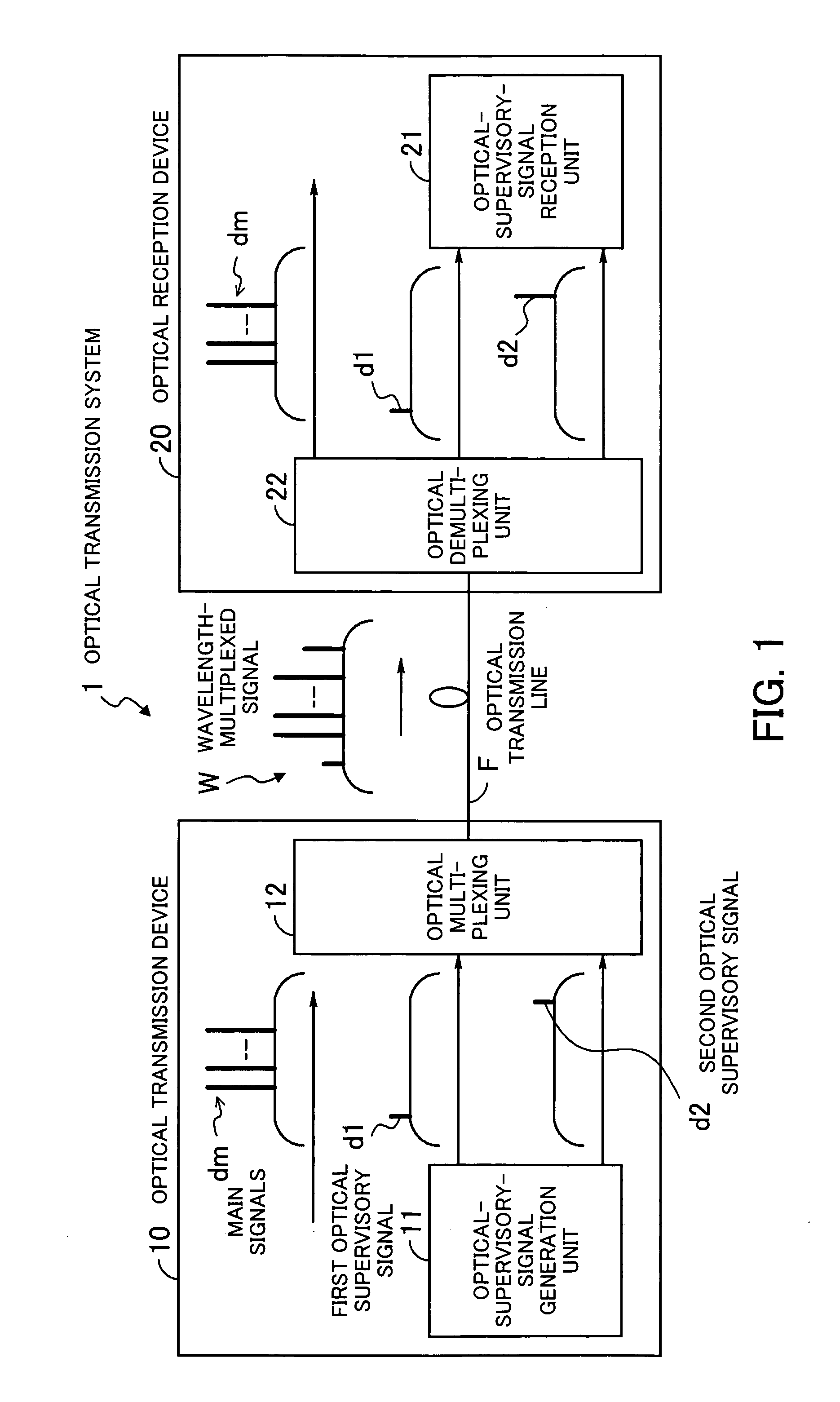
[0032]FIG. 1 is a diagram illustrating the principle of an optical transmission system according to the present invention. The optical transmission system 1 according to the present invention is a system for performing WDM optical transmission, and comprises an optical transmission device 10 and an optical reception device 20. Although only a construction for optical transmission in a downstream direction is illustrated in FIG. 1, it is preferable that the optical transmission device 10 also has the functions of the optical reception device 20 and vice versa.

[0033] The optical transmission device 10 comprises an optical-supervisory-signal generation unit 11 (hereinafter referred to as an OSC generation unit) and an optical multiplexing unit 12. The OSC generation unit 11 generates a first optical supervisory signal (hereinafter referred to as a first OSC signal d1) containing transmission-li...


PUM


Abstract

In an optical transmission system: a first unit generates a first optical supervisory signal being arranged on the shorter-wavelength side of main signals and containing information for determining continuity of an optical transmission line and a second optical supervisory signal arranged on the longer-wavelength side of the main signals and used for supervisory control of optical communication; a second unit generates a wavelength-multiplexed signal by optically multiplexing the main signals and the first and second optical supervisory signals, and transmits the wavelength-multiplexed signal onto the optical transmission line; a third unit receives the wavelength-multiplexed signal, and optically demultiplexes the wavelength-multiplexed signal into the main signals and the first and second optical supervisory signals; and a fourth unit determines whether or not the optical transmission line is optically continuous, based on the first optical supervisory signal, and performs supervisory control of optical communication based on the second optical supervisory signal.

Description

BACKGROUND OF THE INVENTION [0001] 1) Field of the Invention [0002] The present invention relates to an optical transmission system. In particular, the present invention relates to an optical transmission system which performs WDM (Wavelength Division Multiplex) transmission of optical signals. [0003] 2) Description of the Related Art [0004] The WDM technology is a widely used, core technology for optical transmission systems. According to WDM, signals in a plurality of channels are concurrently transmitted through a single optical fiber by multiplexing light having different wavelengths. In WDM systems, optical supervisory signals having a bandwidth of about 1.5 to 150 Mb / s and being called OSC (Optical Supervisory Channel) signals are transmitted as well as main signals having a bandwidth of 2.4 to 40 Gb / s. [0005] The OSC signals are optical signals used for detection of troubles in transmission lines as well as condition monitoring and setting for administration, e.g., condition ...

Claims


Application Information

Patent Timeline
IPC IPC(8): H04B10/07H04B10/077H04B10/079H04B17/00H04J14/00H04J14/02
CPCH04B10/0775H04B2210/077H04B2210/078H04L7/0075H04J14/0275H04J14/0279H04L7/0008H04B2210/08
Inventor TAKAHASHI, TSUKASA
Owner FUJITSU LTD
Why Eureka
Try Eureka