Wind-energy installation comprising a ring generator

a technology of wind power installation and generator, which is applied in the direction of wind power generation, electric generator control, machines/engines, etc., can solve the problems of high mechanical stress on the installation, constant and high load on the wind power installation

Inactive Publication Date: 2005-02-24
WOBBEN ALOYS
View PDF37 Cites 5 Cited by
  • Summary
  • Abstract
  • Description
  • Claims
  • Application Information

AI Technical Summary

Benefits of technology

[0010] Therefore one object of the present invention is to provide a stator having a winding, in which the above-discussed problems are substantially reduced.

Problems solved by technology

It will be appreciated however that wind power installations are always exposed to high levels of loading during operation thereof.
That means that the stress on the wind power installation increases substantially simultaneously, from the mechanical and the electrical point of view.
At high wind speeds the mechanical stress on the installation is high and at the same time a great deal of electrical power is generated so that the stress on the electrical components is also high.
In that situation, the generator of the wind power installation, which is subjected to mechanical and electrical stresses, is particularly stressed.
That combination gives rise to problems if for example, as a consequence of high electric currents generated, the temperature in the region of the generator is also high and, as a consequence of mechanical stress, connections between individual components are subjected to the effect of vibration.
If thermal expansion also gives rise to a small amount of play or a loosening effect, the mechanical loadings can here result in a defect or even damage.
If that trouble involves the stator winding or a phase thereof, at least that phase is out of commission in terms of energy production.
Having regard to statistical probabilities (of no matter how small magnitude), the high number of connecting locations and the permanent changes in load mean that, even if the connection between the former-wound coils is carefully made, this involves a serious source of trouble.

Method used


Image

  • Wind-energy installation comprising a ring generator
  • Wind-energy installation comprising a ring generator
  • Wind-energy installation comprising a ring generator

Examples


Embodiment Construction

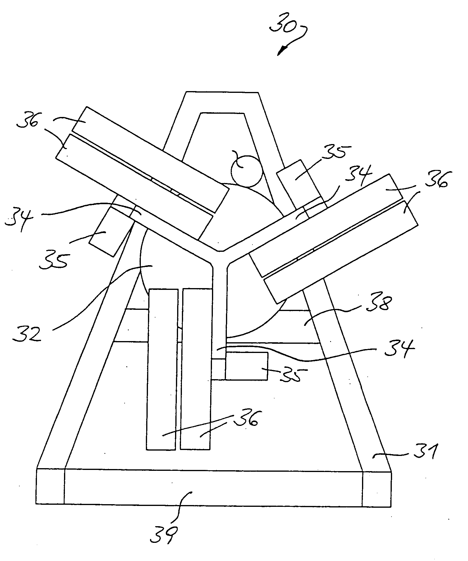
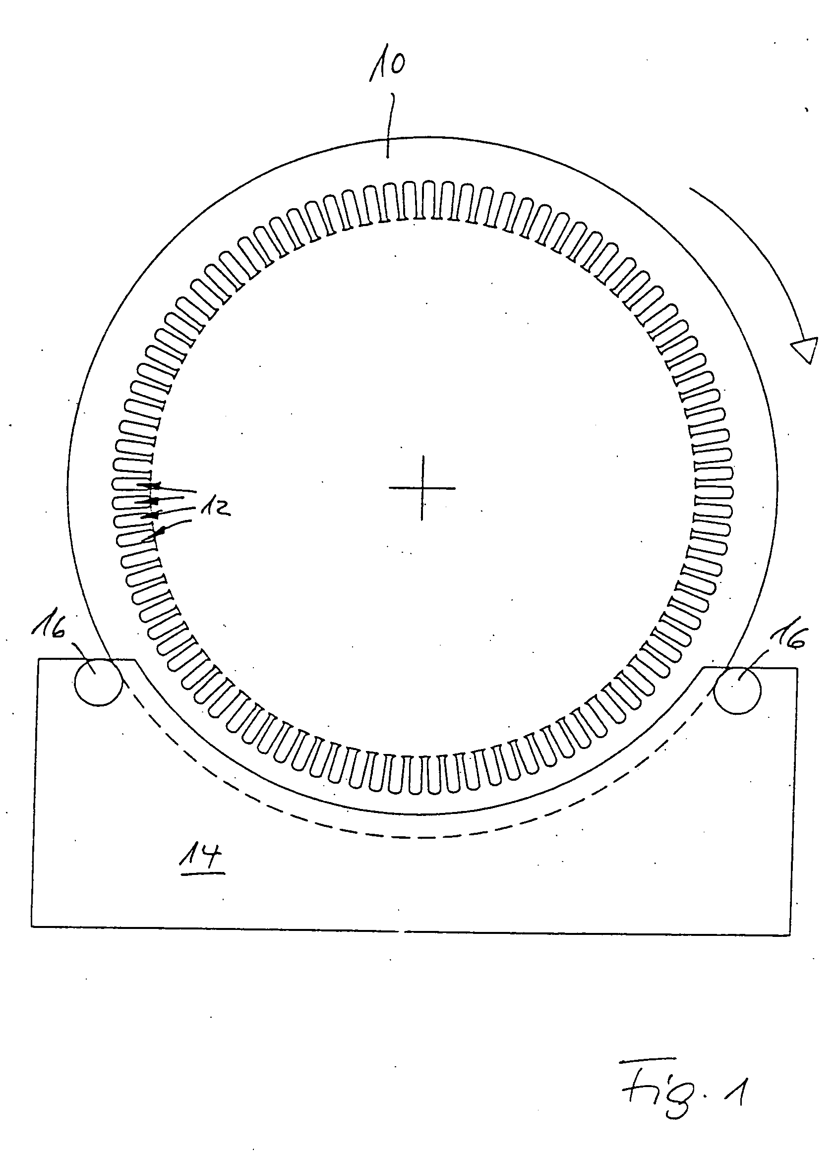
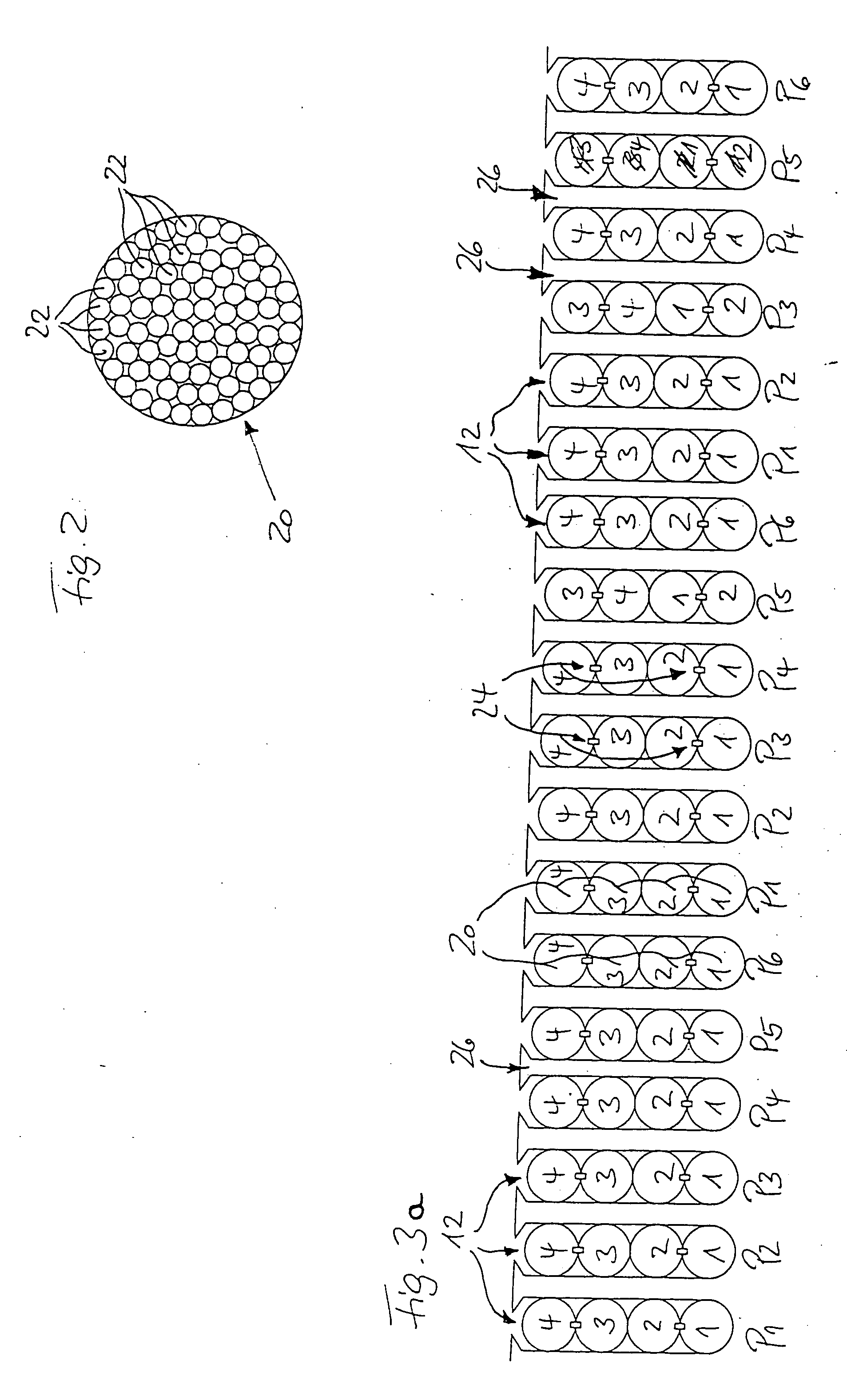
[0029] In FIG. 1 reference numeral 10 denotes the stator which has grooves 12 extending in the axial direction at the inner periphery. That is the most frequent structural configuration of a generator. The rotor (not shown) is within the stator 10. That structural configuration is referred to as an internal rotor. Alternatively, in the case of a so-called external rotor in which the rotor encloses the stator 10, the grooves 12 can be provided at the outer periphery of the stator. The grooves 12 are shown on an enlarged scale in FIG. 3a. The stator 10 is held in a holding apparatus 14 which stands on the ground and thus holds the stator 10 and in particular the grooves 12 at a height which forms a working position which is favorable in terms of working physiology.

[0030] As such a stator 10 of a ring generator is of a diameter of several meters and accordingly is high in weight, the stator 10 is supported rotatably on rotary mountings 16 and can be rotated for example in the directio...


PUM

PropertyMeasurementUnit
speedaaaaaaaaaa
stressaaaaaaaaaa
mechanicalaaaaaaaaaa

Abstract

The present invention concerns a wind power installation having a (ring) generator which has a stator in which grooves are provided at the inner or outer periphery in mutually spaced relationship to receive a stator winding. In order to provide a stator having a winding, in which the susceptibility to trouble as a consequence of the high loading on the generator is substantially reduced, the stator winding is wound without interruption continuously throughout.

Description

BACKGROUND OF THE INVENTION [0001] 1. Field of the Invention [0002] The present invention concerns a wind power installation having a generator which has a stator in which grooves are provided at the inner or outer periphery in mutually spaced relationship to receive a stator winding. Such wind power installations are known and are produced and marketed for example by ENERCON. [0003] 2. Description of the Related Art [0004] A known process for the production of stator windings in generators includes the use of what are referred to as former-wound coils. Those former-wound coils are individual windings of the stator winding, which are already adapted in respect of their form to the grooves and groove spacings of the stator and which are firstly individually inserted into the grooves and then connected together. [0005] It will be appreciated however that wind power installations are always exposed to high levels of loading during operation thereof. With an increasing wind speed the po...

Claims


Application Information

Patent Timeline
Patent Type & Authority Applications(United States)
IPC IPC(8): F03D9/25H02K3/00H02K3/12H02K3/28H02K3/46H02K3/48H02K7/18H02K15/085H02K17/16H02K19/34
CPCF03D9/002F05B2220/70642H02K3/12H02K3/28H02K15/085H02K2203/15Y10T29/49009H02K7/1838H02K3/14Y10T29/53143Y10T29/53148Y10T29/5187Y02E10/725F03D9/25Y02E10/72F03D9/00
Inventor WOBBEN, ALOYS
Owner WOBBEN ALOYS
Why Eureka
Try Eureka