Method of connecting shaped parts made of plastics material and metal

Active Publication Date: 2005-02-24
LANXESS DEUTDCHLAND GMBH
View PDF4 Cites 25 Cited by
  • Summary
  • Abstract
  • Description
  • Claims
  • Application Information

AI Technical Summary

Benefits of technology

[0006] One aspect of the present invention is to provide a method with which shaped parts made of thermoplastic plastics material ca

Problems solved by technology

The Applicants of the present invention realized that the process has the disadvantage, however, that only minimal adhesion is in most cases achieved between the metal components and the plastics components, so that

Method used


Image

  • Method of connecting shaped parts made of plastics material and metal
  • Method of connecting shaped parts made of plastics material and metal
  • Method of connecting shaped parts made of plastics material and metal

Examples


Example

EXAMPLE

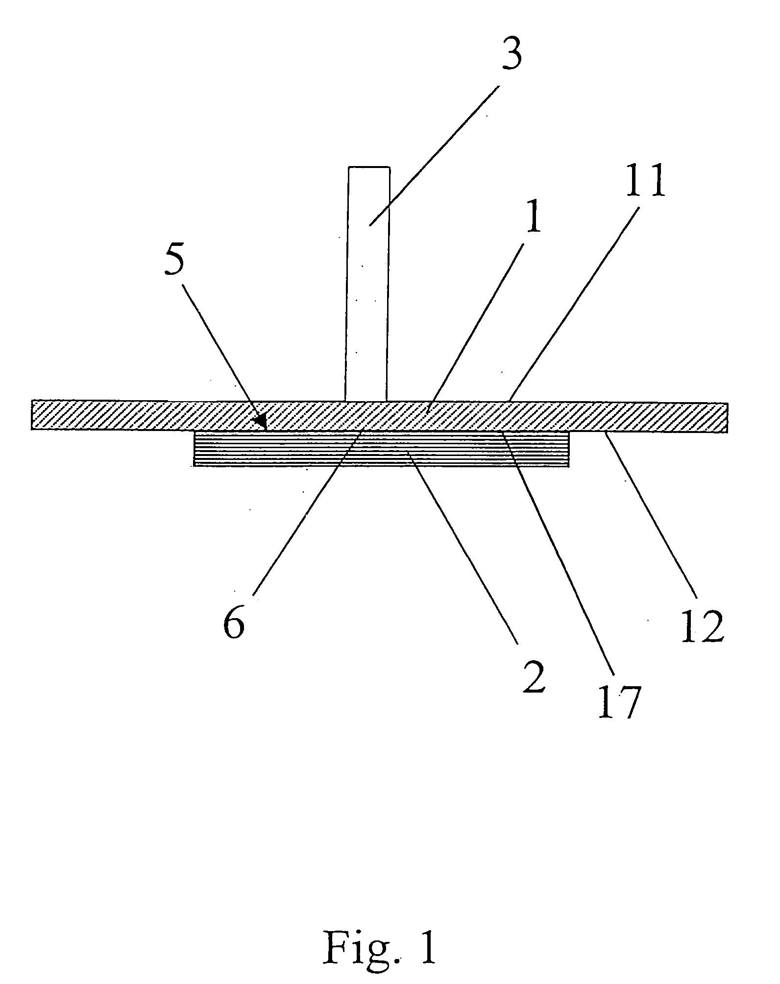
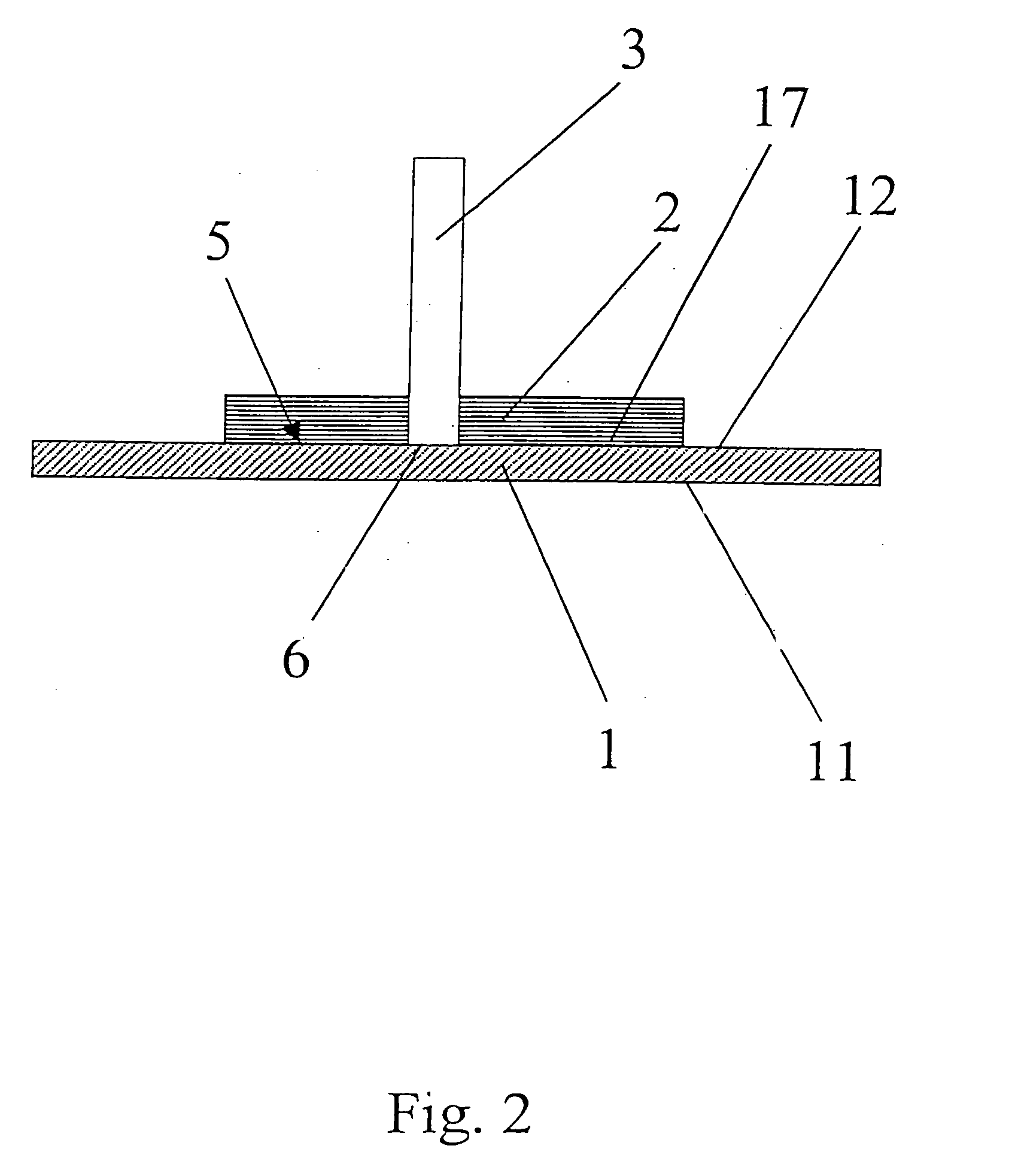
[0045] A shaped metal part 1 made of ST37 steel was connected to a shaped thermoplastic part 2 made of unreinforced polyamide 6 (Durethan® B 30S from Bayer AG) by means of direct laser irradiation, as depicted diagrammatically in FIG. 1. The surface 12 of the metal shaped part 1 facing the plastics shaped part 2 had been phosphated (not shown in FIG. 1). The thickness of the metal shaped part 1 was 0.8 mm, the thickness of the plastics shaped part 2 was 1.2 mm.

[0046] The laser used was a Nd: Yag having a wavelength of 1064 nm and a power of 60 W.

[0047] In tests to determine the strength of the connection between the two shaped parts 1 and 2 (which had been fixedly joined in accordance with the method of the present invention), the tear strengths were found to be in the range of from 126 to 324 N.

[0048] Although the invention has been described in detail in the foregoing for the purpose of illustration, it is to be understood that such detail is solely for that purpose and...


PUM

PropertyMeasurementUnit
Nanoscale particle sizeaaaaaaaaaa
Wavelengthaaaaaaaaaa
Thermoplasticityaaaaaaaaaa

Abstract

A method of connecting (fixedly joining/attaching) a shaped metal part and a shaped thermoplastics part together is disclosed. The method includes: (a) contacting a surface of the shaped metal part with a surface of the shaped thermoplastic part, thereby forming a contact region; and (b) melting a portion of the shaped thermoplastic part in the contact region by irradiating the shaped metal part with a laser (e.g., emitting a laser beam), thereby fixedly joining the shaped metal part and said shaped thermoplastic part together. Also disclosed is a plastic/metal composite article prepared by the method of the present invention.

Description

CROSS REFERENCE TO RELATED PATENT APPLICATION [0001] The present patent application claims the right of priority under 35 U.S.C. § 119 (a)-(d) of German Patent Application No. 103 38 588.6, filed Aug. 26, 2003. FIELD OF THE INVENTION [0002] The invention relates to a method of connecting at least one shaped part made of metal and at least one shaped part made of plastics material, by irradiating the shaped metal part with a laser in a contact region between the shaped plastic and metal parts. BACKGROUND OF THE INVENTION [0003] Plastics / metal composite components which are produced by the injection molding of thermoplastic plastics material around functional elements have recently become widely used in the automotive and electrical industry. Components for electrical applications, in which contact ducts through a housing wall are required, e.g., automotive fuse boxes or sensor housings, may be produced by the process of direct injection molding around elements. In such processes, a t...

Claims


Application Information

Patent Timeline
IPC IPC(8): B23K26/40B29C37/00B29C65/00B29C65/16
CPCB23K26/4005Y10T156/10B23K26/402B23K26/4065B23K26/4085B23K26/409B29C37/0082B29C65/1612B29C65/1616B29C65/1635B29C65/1674B29C65/1683B29C65/44B29C66/30321B29C66/472B29C66/71B29C66/7392B29C66/742B29C66/7422B29C66/74281B29C66/74283B29C2791/009B23K26/401Y10T29/49968Y10T29/49906B29C65/1629B29L2031/3055B29K2025/06B29K2027/06B29K2023/06B29K2069/00B29K2077/00B29K2071/00B29K2023/00B29K2059/00B29K2023/12B29K2067/00B29K2079/08B23K26/40B29C65/168B29C66/02245B29C66/1122B29C66/721B29C66/7212B29C66/73161B23K2103/02B23K2103/04B23K2103/10B23K2103/12B23K2103/16B23K2103/172B23K2103/18B23K2103/42B23K2103/50Y10T428/31504B29K2307/04B29K2309/08B29K2023/04B29K2023/10B29K2025/04B29K2075/00B29K2067/006B29K2081/04B29K2055/02B29K2071/12B29K2067/003B29K2025/08
Inventor KRAUSE, FRANKJOACHIMI, DETLEV
Owner LANXESS DEUTDCHLAND GMBH
Why Eureka
Try Eureka