Fluidic functions based on non-wettable surfaces

a technology of fluoropolymer and non-wettable surface, which is applied in the direction of immunoassays, material testing goods, withdrawal sample devices, etc., can solve the problems of negative affecting the flow-controlling function of a local non-wettable surface area and the risk of insufficient function, so as to reduce the risk of failure and increase the adhesion of fluoropolymers.

Inactive Publication Date: 2005-02-24
GYROS
View PDF43 Cites 90 Cited by
  • Summary
  • Abstract
  • Description
  • Claims
  • Application Information

AI Technical Summary

Benefits of technology

Other objects lower the risk for failure of microfluidic functions that are based on non-wettable surface breaks. This object is primarily applicable to protocols in which a liquid aliquot is passing a fluidic function that comprises a non-wettable surface break subsequent to the passage of a liquid aliquot that contains the above-mentioned destabilizing components.
Yet further, another object is to increase the adherence of fluoropolymers to plastic surfaces, in particular to wettable plastic surfaces including plastic surfaces the wettability of which has been increased (hydrophilized).

Problems solved by technology

This may negatively affect the flow-controlling function of a local non-wettable surface area due to adsorption of surface-active components to the area (drawback 1) and / or destruction / degrading of the area by action of “aggressive” components in the liquid in the case the area is in the form of a coat (drawback 2).
Both drawbacks mean a risk for insufficient function next time the local non-wettable surface area / function is contacted with liquid.

Method used


Image

  • Fluidic functions based on non-wettable surfaces
  • Fluidic functions based on non-wettable surfaces
  • Fluidic functions based on non-wettable surfaces

Examples


example 1

Manufacture of Smooth Innovative Non-Wettable Surfaces

MATERIALSChemicalManufacturerDescriptionCytonix ™ PFC-602ACytonix2% fluoroaliphatic polymerin HFE-7100Teflon ™ NP 2400DupontPoly[4,5-difluoro-2,2-bis(tri-fluoromethyl)-1,3-dioxole-co-tetrafluoroethyleneHFE ™-71003MFluorinated solventFC ™-753MFluorinated solvent1H,1H,2H,2H-perfluoro-AldrichFluorinated methacrylatedecylmethacrylate (C10F)MonomerEsacure ™ TZTLambertiUV-initiatorEQUIPMENTInstrumentManufacturerDescriptionGyrolab ™ WorkstationGyros ABWO 02075312,PCT / SE2004 / 000440,PCT / SE2004 / 000441 (all ofGyros AB).PS 500Plasma SciencePlasma reactorEfsen 500W Hg-lampEfsenUV-lamp

Methods

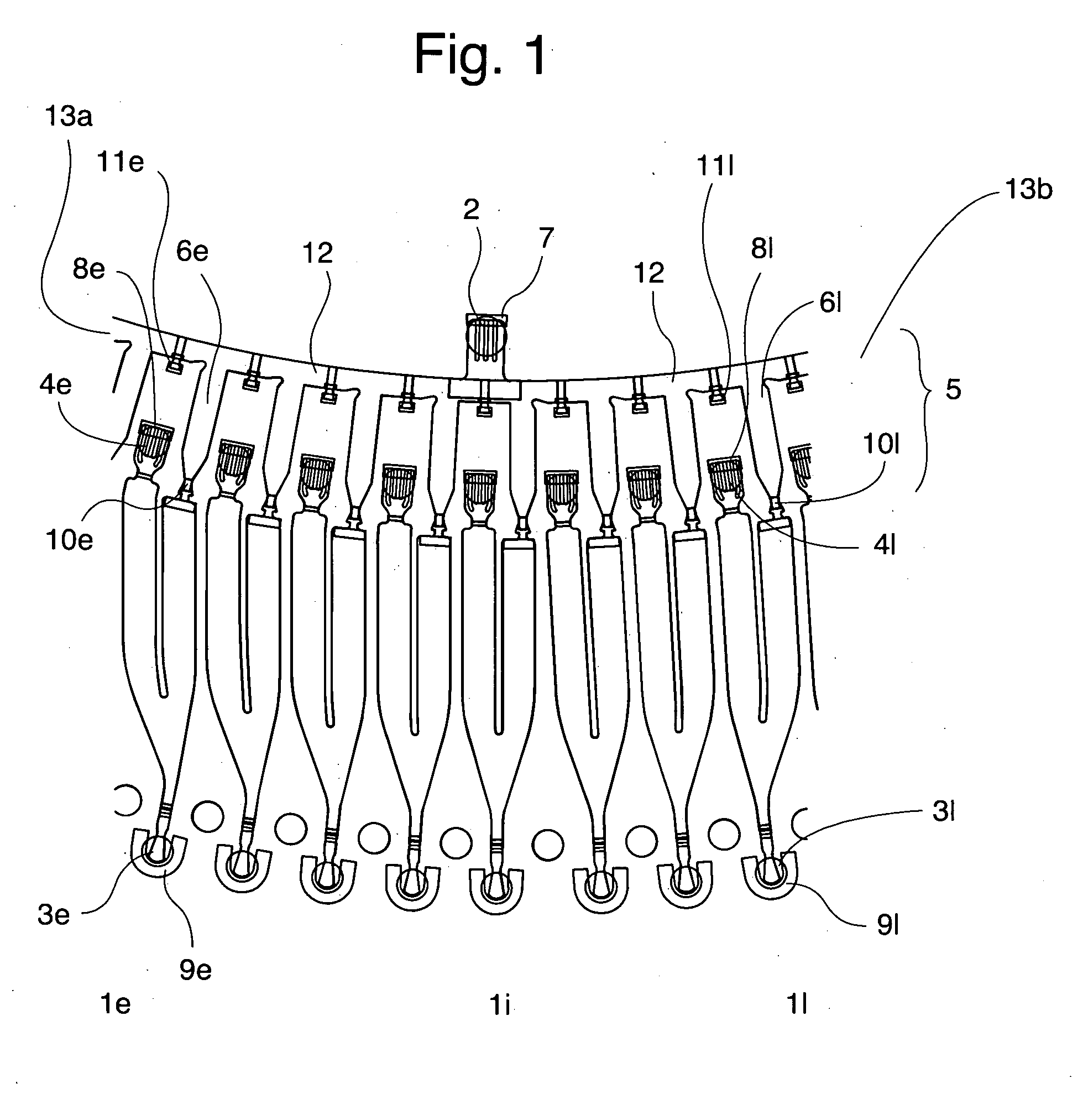
Microfluidic device: The device was in the form of a circular disc of the same size as a conventional CD. The microchannel structures were in principle of the same design and function in the same way as the structures in FIGS. 7a and b in WO 02075775 (which is incorporated herein by reference in its entirety). The main difference is that the CD used to...

example 2

Preparation of Rough Non-Wettable Surfaces

0.4-2.0% (w / w) Aerosil™ R972 methylated silica colloids (DeGussa, d=11 nm) were added to a 0.05% solution of Teflon-AF™ 2400 (DuPont Polymers, DE, USA). The mixture was applied by spraying or dipping onto Zeonor™ 1420R (Zeon Corp., Japan) which had been surface treated with an oxygen plasma (Plasma Electronic, Germany). The resulting surfaces had advancing / receding water contact angles of 165-170° / 130-170°.

2% (w / w) Aerosil™ R972 was added to PFC602A (Cytonix Corp., MD, USA), which is a 2% solution of polyperfluorooctylmethacrylate in HFE-7100 (3M Belgium N.V.). Sprayed or dipped surfaces had advancing / receding water contact angles of 169-174° / ˜165°.

The adhesion of these coatings to oxygen plasma-treated Zeonor™ could be greatly improved by mixing, for example 2% PFC602A in a 1:1 ratio with perfluorodecylmethacrylate and 0.1-0.4% Esacure™ TZT (Lamberti, Italy) and 1% Aerosil™ R972. The mixture required the addition of acetone (10%) in o...


PUM

PropertyMeasurementUnit
roughnessaaaaaaaaaa
water contact anglesaaaaaaaaaa

Abstract

A method for processing two or more liquid aliquots in a microchannnel structure of a microfluidic device. The microchannel structure comprises a hydrophilic microconduit with a fluidic function and a local non-wettable surface associated with the fluidic function/microconduit. Other aspects comprise a method for producing the fluidic function, which comprises introducing non-wettability on a local surface area S that is associated with the microconduit.

Description

TECHNICAL FIELD The present invention relates to a method for processing two or more liquid aliquots in a microchannnel structure of a microfluidic device, typically made in plastics. Further aspects relate to a method for producing the fluidic function. BACKGROUND OF THE INVENTION Boundaries defined between wettable surface areas and non-wettable surface areas in microchannel structures / microconduits have previously been utilized in applications where liquid is to be retained on the wettable sides of these boundaries for shorter or longer periods of time. In microfluidics this kind of boundaries has been used in passive valves, anti-wicking functions, vents, liquid-directing functions etc. Local non-wettable surface areas have typically been introduced by patterning a generally wettable (hydrophilic) surface with a non-wettable (hydrophobic) material. See for instance: WO 9958245, WO 0185602, WO 02074438, WO 03018198, and WO 03024598; U.S. Pat. No. 6,926,020, U.S. Pat. No. 6,591,...

Claims


Application Information

Patent Timeline
Patent Type & Authority Applications(United States)
IPC IPC(8): G01N1/10
CPCB01L3/502738B01L2200/0605B01L2200/0631B01L2200/0647B01L2200/0684B01L2200/12Y10T436/2575B01L2300/0806B01L2300/0864B01L2300/161B01L2400/086B01L2400/088B01L2200/142
Inventor DERAND, HELENEFIELDEN, MATTHEWHELLERMARK, CECILLIAKANGE, RICKARDSENNEFORS, THERESE
Owner GYROS
Why Eureka
Try Eureka