Multi-core multi-thread processor

a multi-thread processor and multi-core technology, applied in the field of servers, can solve the problems of large cache memory requirements, large memory bandwidth for serving applications, and large processors, and achieve the effect of hiding delays caused by cache accesses

Active Publication Date: 2005-02-24
ORACLE INT CORP
View PDF11 Cites 171 Cited by
  • Summary
  • Abstract
  • Description
  • Claims
  • Application Information

AI Technical Summary

Benefits of technology

[0011] In another embodiment, a server is provided. The server includes an application processor chip. The application processor chip includes a plurality of multithreaded central processing unit cores. Each of the plurality of multi-threaded central processing unit cores has a load / store unit. A crossbar is provided. A plurality of cache bank memories in communication with the at least two cores through the crossbar is included. Each of the plurality of cache bank memories is in communication with a main memory interface. A plurality of input / output (I / O) interface modules are in communication with the main memory interface and provide a link to the at least two cores. The link bypasses the plurality of cache bank memories and the crossbar. The threading hardware is configured to enable each of the at least two cores to switch from a first thread to a second thread in a manner hiding delays caused by cache accesses.

Problems solved by technology

In particular, the serving applications require large memory bandwidth and large cache memory requirements in order to accommodate a large number of clients.
Therefore, the processors tend to be very large and the pipeline is very complex.
Consequently, due to the complexity of the pipeline for processors, such as INTEL processors, only one core is on the die.
Accordingly, when there is a cache miss or some other long latency event, there is usually a stall that causes the pipeline to sit idle.
Thus, the characteristics of implementation for conventional processors with the application of serving workloads result in a poor fit since conventional processors focus on instruction level parallelism.

Method used


Image

  • Multi-core multi-thread processor
  • Multi-core multi-thread processor
  • Multi-core multi-thread processor

Examples


Embodiment Construction

[0023] An invention is described for an apparatus and method for transmitting data between two processors in a manner that maintains line rate throughput. It will be obvious, however, to one skilled in the art, that the present invention may be practiced without some or all of these specific details. In other instances, well known process operations have not been described in detail in order not to unnecessarily obscure the present invention.

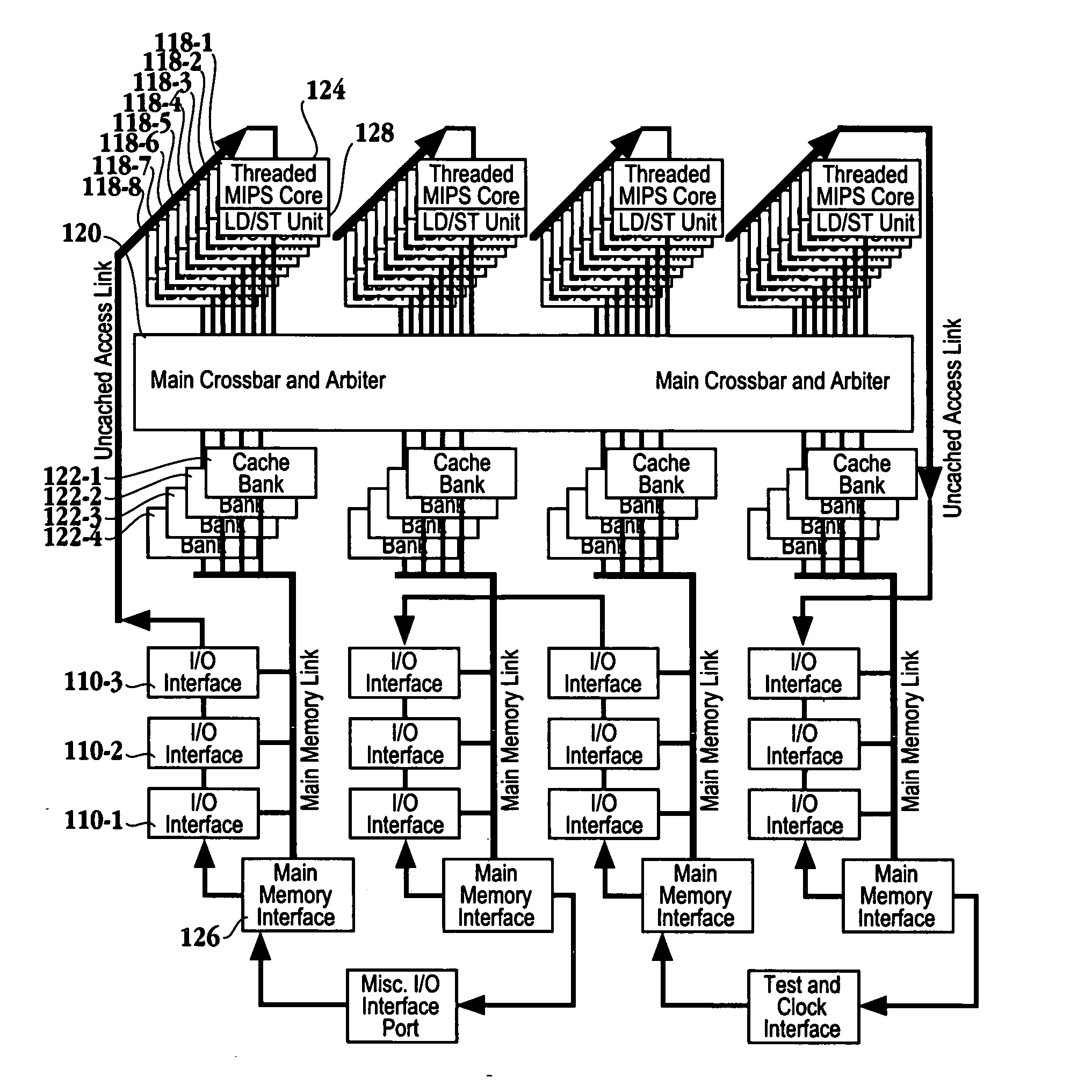
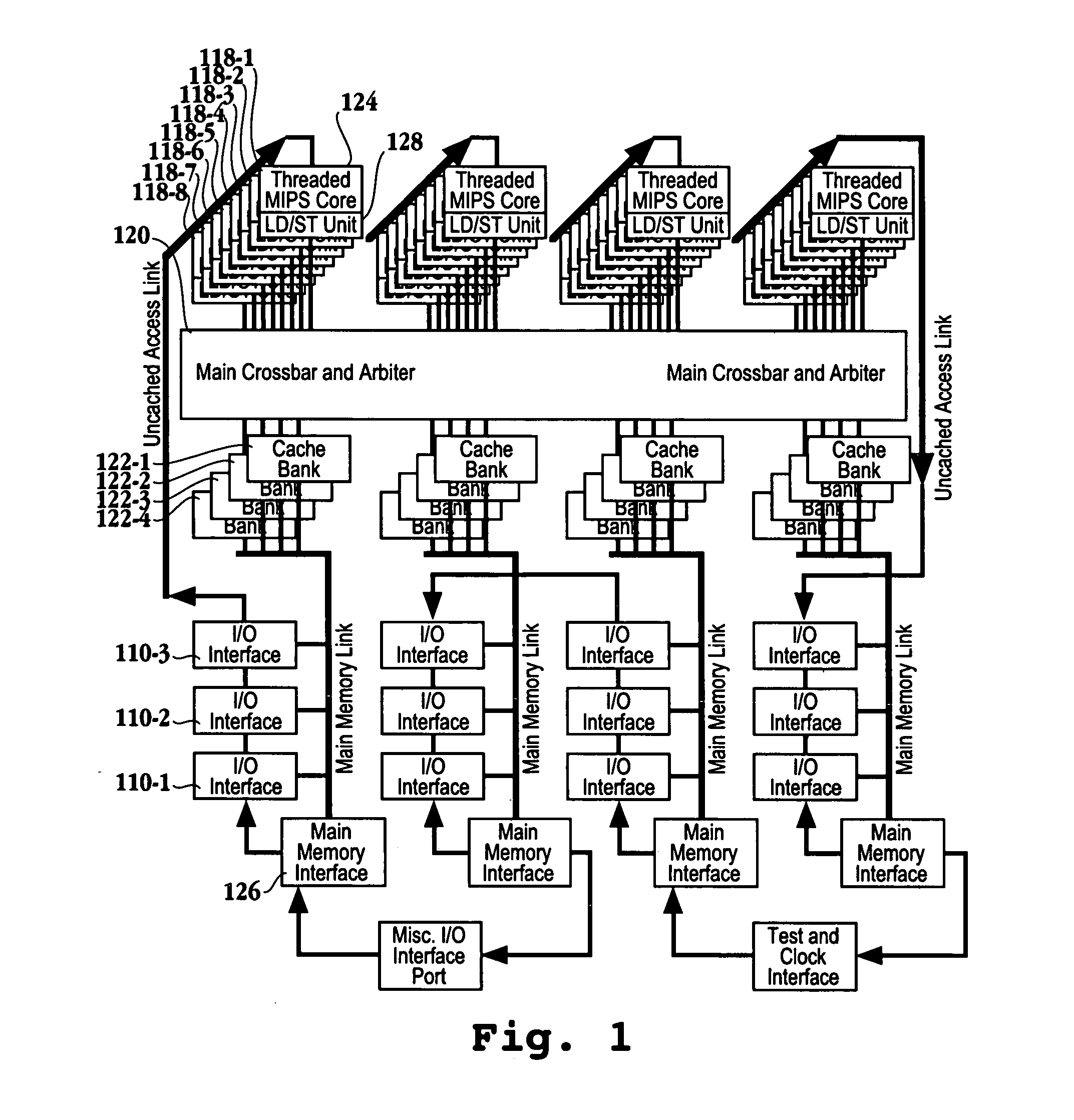
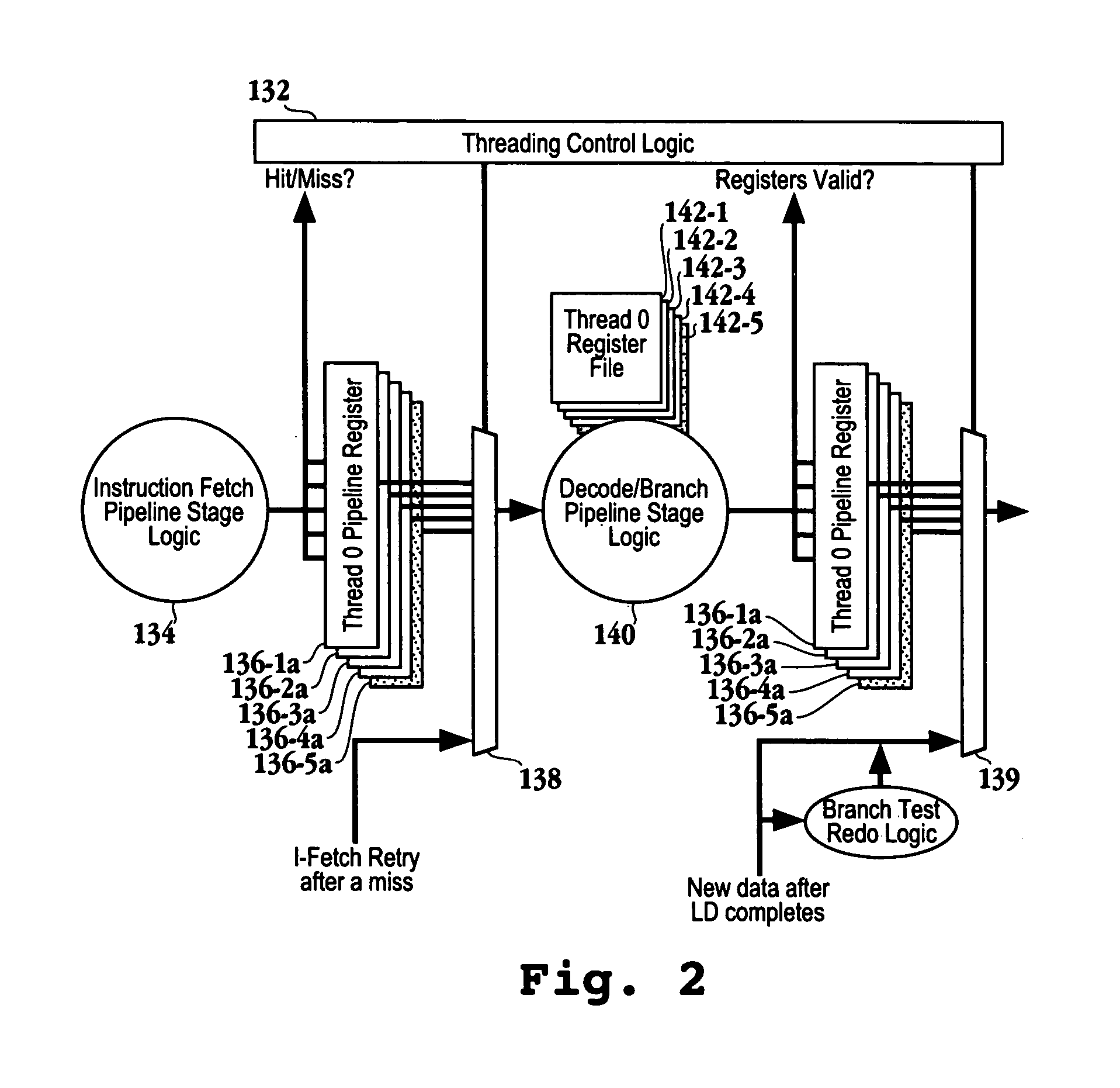
[0024] The embodiments described herein have multiple simple cores on a chip, where each of the cores have their own first level cache and the cores share a second level cache through a crossbar. Additionally, each of the cores have two or more threads. Through multi-threading, latencies due to memory loads, cache misses, branches, and other long latency events are hidden. In one embodiment, long latency instructions cause a thread to be suspended until the result of that instruction is ready. One of the remaining ready to run threads on the co...


PUM


Abstract

A processor is provided. The processor includes at least two cores. The at least two cores have a first level cache memory and are multi-threaded. A crossbar is included. A plurality of cache bank memories in communication with the at least two cores through the crossbar is provided. Each of the plurality of cache bank memories communicates with a main memory interface. A plurality of input / output interface modules in communication with the main memory interface and providing a link to the at least two cores are included. The link bypasses the plurality of cache bank memories and the crossbar. Threading hardware configured to enable the at least two cores to switch from a first thread to a second thread in a manner hiding delays caused by cache accesses is included. A server and a method for determining when to switch threads in a multi-core multi-thread environment are included.

Description

CROSS REFERENCE TO RELATED APPLICATIONS [0001] This application claims priority from U.S. Provisional Patent Application No. 60 / 496,602 filed Aug. 19, 2003 and entitled “WEB SYSTEM SWERVER DESIGN SPECIFICATION”. This provisional application is herein incorporated by reference.BACKGROUND OF THE INVENTION [0002] 1. Field of the Invention [0003] This invention relates generally to servers and more particularly to a processor architecture and method for serving data to client computers over a network. [0004] 2. Description of the Related Art [0005] With the networking explosion brought along with introduction of the Internet, there has been a shift from the single thread desktop applications for personal computers to server applications that have multiple threads for serving multiple clients. Electronic commerce has created a need for large enterprises to serve potentially millions of customers. In order to support this overwhelming demand, the serving applications require different mem...

Claims


Application Information

Patent Timeline
Patent Type & Authority Applications(United States)
IPC IPC(8): G06F9/30G06F9/315G06F9/38G06F12/08G06F15/78
CPCG06F9/30032G06F9/30047G06F9/30087G06F9/3009G06F9/30141G06F9/3828G06F15/7846G06F9/3851G06F9/3861G06F9/3891G06F12/0811G06F12/0813G06F12/0842G06F9/3834G06F15/167G06F15/781
Inventor OLUKOTUN, KUNLE A.
Owner ORACLE INT CORP
Why Eureka
Try Eureka