
Two temperature two stage forming

Active Publication Date: 2005-03-03
GM GLOBAL TECH OPERATIONS LLC
View PDF9 Cites 10 Cited by
  • Summary
  • Abstract
  • Description
  • Claims
  • Application Information

AI Technical Summary

Benefits of technology

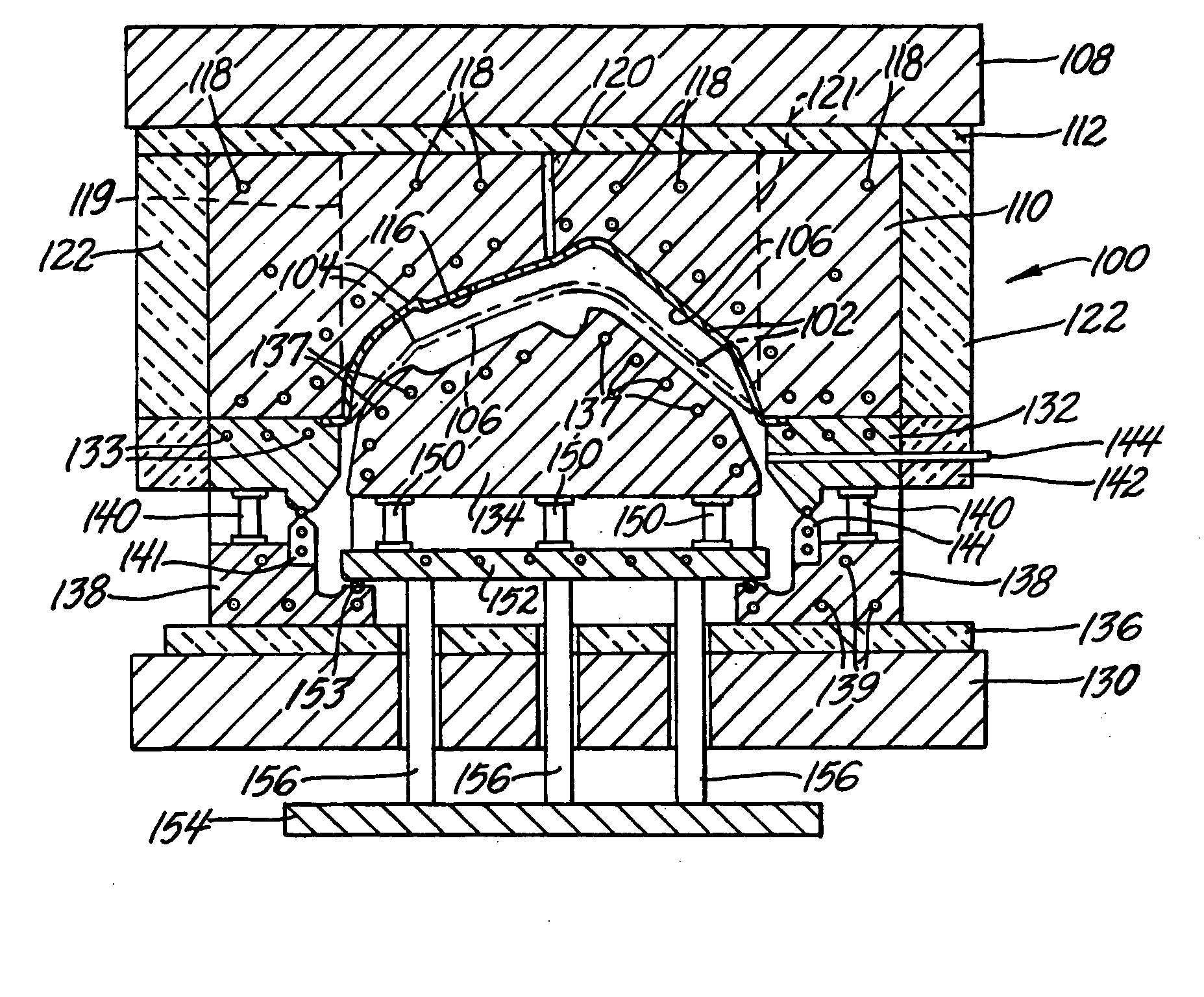
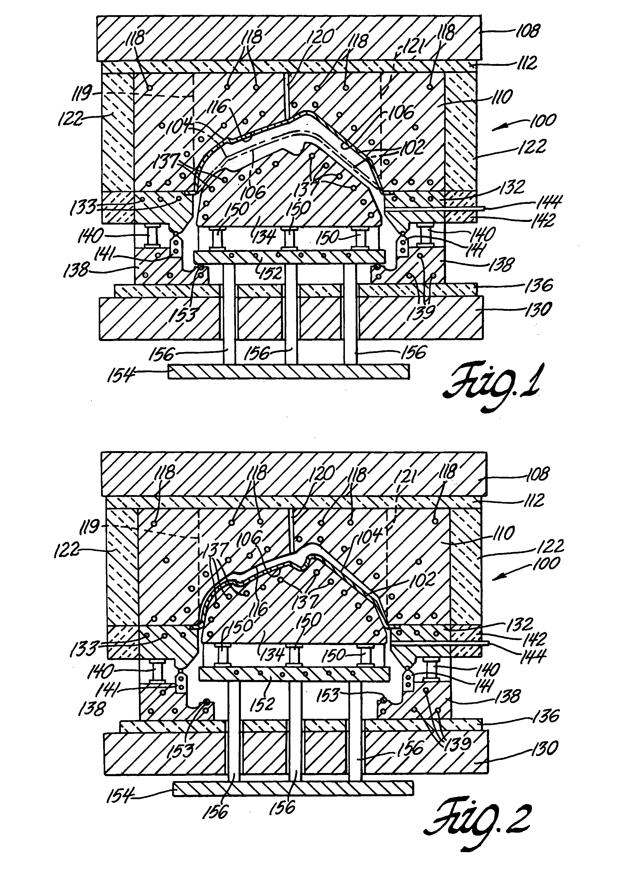
[0008] Briefly stated, the preforming tool is maintained at a relatively high temperature to facilitate rapid plastic elongation of the sheet material as it is stretched under suitable working gas pressure and ballooned against the surface of the preform tool. The preform tool preferably has a concave surface to receive the ballooning blank. The relatively high temperature of the preform tool surface permits the preheated blank to be initially shaped at a relatively high strain rate for the sheet metal alloy. A purpose of the higher preform temperature is to use a lower working gas pressure, consistent with a high strain rate, which permits more rapid venting of the preform gas. Thus, the preform step introduces substantial elongation in the blank by establishing a gross shape approximating the final shape of the part. Such preforming permits the final forming of the detailed bends, curvatures and other shape features in the final part without tearing or marring of the formed part.
[0009] The temperature of the finish-form tool surface is lower than the surface of the preform tool. This means that the preform part experiences some cooling as it is pushed from the preform tool to the finish form tool. The finish-form step is carried out at a somewhat lower temperature at which the sheet metal retains suitable ductility for final forming but also achieves more rigidity for distortion-free removal of the part from the finish-form tool.

Problems solved by technology

The overall process has remained slow for high volume production operations.

Method used


Image

  • Two temperature two stage forming
  • Two temperature two stage forming

Examples


Embodiment Construction

[0015] This invention has application in the two-stage stretch forming of a heated sheet metal work piece in a process where pressurized air or nitrogen is applied first to one side of the workpiece and then the other side to first stretch it against a heated preform tool and then against a heated finish form tool. As described in the above referenced U.S. patent application, articles of complex shape such as automobile body panels can be made by such a practice using suitable high elongation alloys.

[0016] For purposes of illustration the practice of this invention will be described in the quick plastic forming of fine grained, superplastically formable AA5083 sheet material about 1.5 mm in thickness. Suitable press and tooling apparatus will be described for the practice of a preferred embodiment of the method of this invention.

[0017]FIGS. 1 and 2 are schematic illustrations in cross section of an elevation view of press platens and two complementary, but not mating, forming tool...


PUM

PropertyMeasurementUnit
Temperatureaaaaaaaaaa

Abstract

A method is disclosed for two-stage stretch forming of a sheet metal blank workpiece between a preform tool with a concave cavity and an opposing finish-form punch tool. Both tools are independently heated to different forming temperatures with the preform tool being hotter. Gas pressure is first applied to one side of the workpiece in the first forming stage to balloon it into the cavity of the preform tool. Gas pressure is then applied to the other side of the preformed workpiece to stretch it against the finish-form surface. The hotter preform tool enables faster forming and gas venting in the first stage. The cooler finish-form tool enables the final shaping of the part and its undistorted removal from the punch surface.

Description

TECHNICAL FIELD [0001] This invention pertains to hot stretch forming of a sheet metal blank between a preform tool (first stage) and then a final-form tool (second stage). More specifically, this invention pertains to such two stage stretch forming where the preform tool is maintained at a higher forming temperature than the final-form tool. This enables faster forming in the preform stage and distortion-free removal of the part from the final-form tool. BACKGROUND OF THE INVENTION [0002] Automotive body panels can be made by sheet metal stretch forming processes that use complementary, double action forming tools in a press and the pressure of a working gas to stretch form a preheated blank against the forming surfaces. In one embodiment, the process is applicable to stretch forming of a superplastically formable or quick plastically formable metal alloy blank into a sheet metal product of complex shape. The metal alloy may, for example, be a magnesium-containing, aluminum alloy h...

Claims


Application Information

Patent Timeline
IPC IPC(8): B21D22/02B21D26/02
CPCB21D22/02B21D26/025B21D37/16B21D26/055B21D26/031
Inventor SCHROTH, JAMES GREGORY
Owner GM GLOBAL TECH OPERATIONS LLC
Learn More